5.4 OUTPUT SIGNALS
0
1
2
3
4
5
6
7
POWER - 12V
USB
OPTICAL SEL.
12345
123
456
76
8
UPGRADEPRESETS
SPEAKER
OUT
OPTICAL IN
DRC
SUB OUT
INPUTS
ASP
OFF ON
REM IN
REM OUT
MASTER ENABLE
30A
16: White OUT 1+
15: White OUT 2+
14: White OUT 3+
13: White OUT 4+
12: White OUT 5+
11: White OUT 6+
10: White OUT 7+
9: White OUT 8+
8: White/Black OUT 1-
7: White/Black OUT 2-
6: White/Black OUT 3-
5: White/Black OUT 4-
4: White/Black OUT 5-
3: White/Black OUT 6-
2: White/Black OUT 7-
1: White/Black OUT 8-
2
1
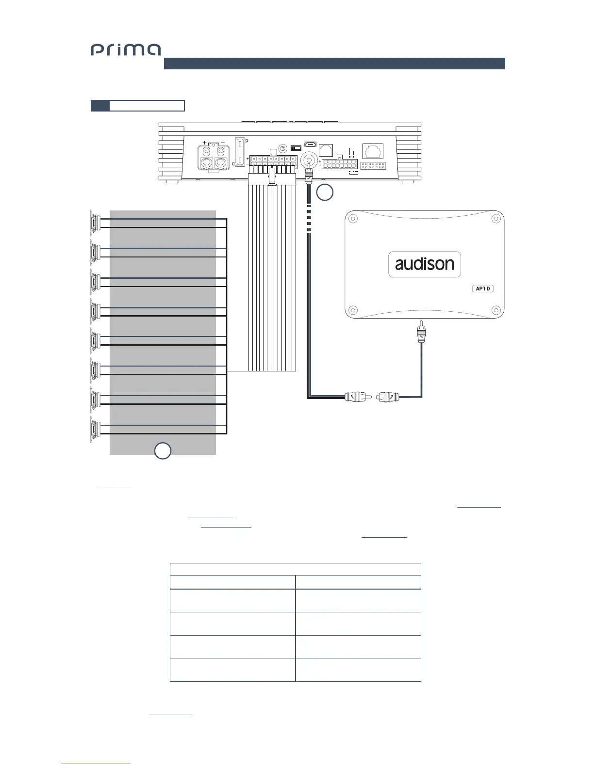
1. AP8.9 bit provides 8 amplified outputs. Through the PC Software, each output channel has the following available
(ee sec. 7.2):
- a 10 pole graphic equalizer;
- a 68-frequency electronic crossover and Butterworth or Linkwitz-Riley type filters with 6-24 dB slopes
(see sec. 7.3.10);
- a digital time delay line
(see sec. 7.3.11);
- Phase inversion activation
(see sec. 7.3.10.2);
- Adjustment of the output level to better align the total system response
(see sec. 7.3.13);
2. AP8.9 bit features one a preamplified output (4 V Rms max.) SUB OUT that exclusively controls a mono amplifier
for subwoofer, or one active subwoofer to amplify the sound system. This output can be activated during I/O Wizard
Configuration (see sec. 7.2.9).
STEREO MODE
POWER CHANNEL CONFIG
BRIDGE MODE
CH1 35 W @ 4 Ohm / 65 W @ 2 Ohm
CH2 35 W @ 4 Ohm / 65 W @ 2 Ohm
CH3 35 W @ 4 Ohm / 65 W @ 2 Ohm
CH4 35 W @ 4 Ohm / 65 W @ 2 Ohm
CH5 35 W @ 4 Ohm / 65 W @ 2 Ohm
CH6 35 W @ 4 Ohm / 65 W @ 2 Ohm
CH7 35 W @ 4 Ohm / 65 W @ 2 Ohm
CH8 35 W @ 4 Ohm / 65 W @ 2 Ohm
CH1+ / CH2- 130 W @ 4 Ohm
CH3+ / CH4- 130 W @ 4 Ohm
CH5+ / CH6- 130 W @ 4 Ohm
CH7+ / CH8- 130 W @ 4 Ohm
5
CH 1÷CH 8 AMPLIFIED OUTPUT CHANNELS CONFIGURATION