Hazardous voltage!
Risk of electric shock.
→
Disconnect device from the mains before opening.
1. Loosen screws [2] and remove cover [1].
2. Insert cable glands suitable for connecting cables.
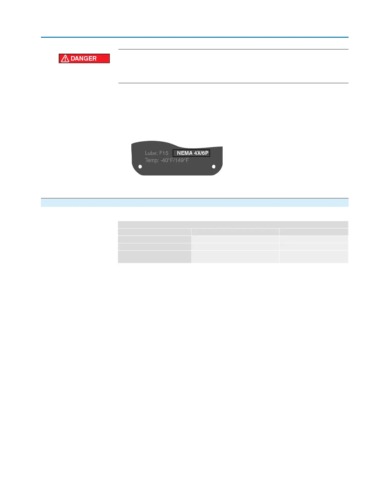
Information: When selecting cable glands observe type of protection (with Ex d
approval) and type of protection NEMA... (refer to name tag).
The type of protection stated on the name tag NEMA... is only ensured, if suitable
cable glands are used.
Figure 14: Example: Name tag for enclosure protection NEMA
3. Seal unused cable entries with approved plugs suitable for the required protection
type.
5.2.2. Cable connection
Table 5:
Terminal cross sections and terminal tightening torques
Tightening torquesTerminal cross sectionsDesignation
1.1 – 1.3 ft-lb [1.5 – 1.8 Nm]max. 10 mm² (flexible or solid)Power terminals (U, V, W)
2.2 – 2.9 ft-lb [3.0 – 4.0 Nm]max. 10 mm² (flexible or solid)PE connection
0.4 – 0.6 ft-lb [0.6 – 0.8 Nm]max. 2.5 mm² flexible, or
max. 4 mm² solid
Control contacts (1 to 50)
1. Remove cable sheathing and insert the wires into the cable glands.
2. Fasten cable glands with the specified torque to ensure required enclosure protec-
tion.
3. Strip wires.
4. For flexible cables: Use wire end sleeves.
5. Connect cables according to order-related wiring diagram.
21
SAEx 07.2 – SAEx 16.2 / SAREx 07.2 – SAREx 16.2
Electrical connection

 Loading...


