9.5.2. Limit switch checking
1. Move actuator manually into both end positions of the valve.
➥
The limit switches are set correctly if:
- LSC switch trips in end position CLOSED
- LSO switch trips in end position OPEN
- the switches release the contacts after turning back the handwheel
2. If the end position setting is incorrect: Reset limit switches.
3. If the end position setting is correct and no options (e.g. potentiometer, position
transmitter) are available: Close switch compartment.
9.6. EWG 01.1 electronic position transmitter
— Option —
EWG 01.1 electronic position transmitter signals the remote position or the valve position.
On the basis of the actual valve position sensed by hall sensor, a current signal between
0 – 20 mA or 4 – 20 mA is generated.
Technical data
Table 7: EWG 01.1
2-wire system3-wire and 4-wire systemsData
4 – 20 mA0 – 20 mA, 4 – 20 mAOutput current I
a
24 V DC (18 – 32 V)24 V DC (18 – 32 V)Power supply U
V
1)
20 mALED off = 26 mA, LED on = 27 mAMax. current consumption
(U
V
– 12 V)/20 mA
600 Ω
Max. load R
B
0.1 %Impact of power supply
0.1 %Load influence
< 0.1 ‰/KTemperature impact
–76 °F to 176 °F (–60 °C to +80 °C)Ambient temperature
2)
Power supply possible via: AC, AM controls or external power supply1)
Depending on temperature range of the actuator: Refer to name tag2)
Setting components
The EWG is housed in the actuator switch compartment.The switch compartment must
be opened to perform any settings. Refer to <Switch compartment: open>.
All settings are made via the two push buttons [S1] and [S2].
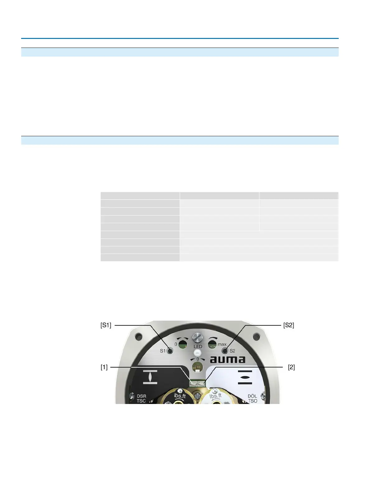
Figure 25: View on control unit when switch compartment is open
[S1] Push button: Set 0/4 mA
[S2] Push button: Set 20 mA
LED Optical aid for setting
[1] Measuring point (+) 0/4 – 20 mA
[2] Measuring point (–) 0/4 – 20 mA
34
SAEx 07.2 – SAEx 16.2 / SAREx 07.2 – SAREx 16.2
Commissioning

 Loading...


