1. Refer to table and check if turns/stroke correspond to the setting of the reduction
gearing (stages 1– 9).
Table 26:
Turns of actuator per valve stroke and suitable reduction gearing setting
Reduction gearing
Stage
for 10 – 5,000 turns/stroke
[exceeding – to]
for 1 – 500 turns/stroke
[exceeding – to]
110 – 191.0 – 1.9
219 – 371.9 – 3.7
337 – 793.7 – 7.9
479 – 1507.9 – 15.0
5150 – 31515.0 – 31.5
6315 – 60031.5 – 60.0
7600 – 1,26060.0 – 126
81,250 – 2,500126 – 240
92,500 – 5,000240 – 500
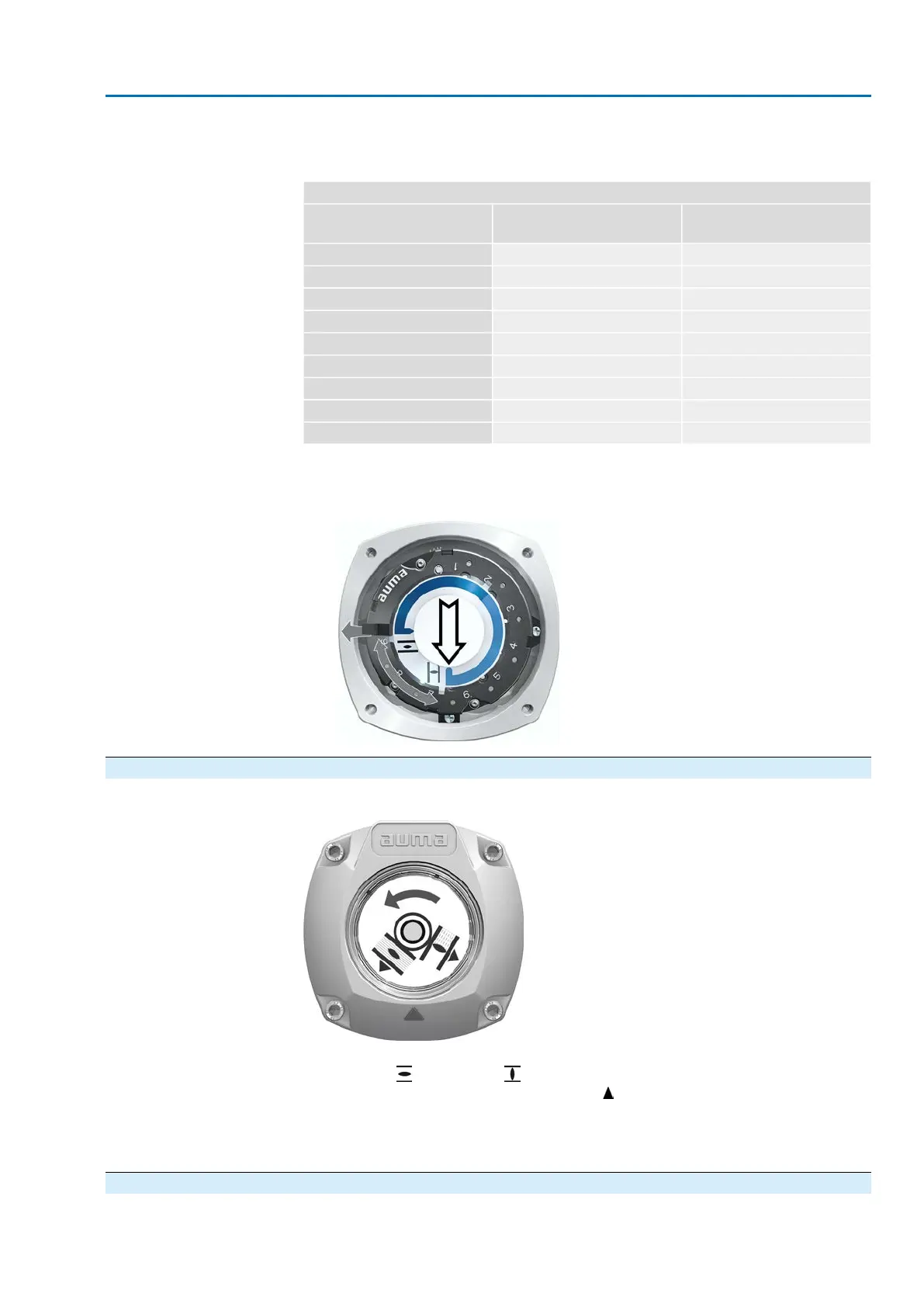
2. To modify settings, lift the lever at the reduction gearing and engage at the se-
lected stage.
Figure 72: Set reduction gearing
10.3. Mechanical position indication via indicator mark (not self-adjusting)
Figure 73: Mechanical position indication via indicator mark
The mechanical position indicator shows the valve position via two indicator discs
with symbols (OPEN) and (CLOSED). When correctly set, the symbols
OPEN/CLOSED point to the indicator mark at the cover in the end positions.
Setting elements
The position indications is housed in the actuator switch compartment. The switch
compartment must be opened to perform any settings. Refer to <Switch compartment:
open/close>.
10.3.1. Mechanical position indicator: set
1. Move valve to end position CLOSED.
69
SAEx 07.2 – SAEx 16.2 / SAREx 07.2 – SAREx 16.2 Control unit: electronic (MWG)
ACExC 01.2 Non-Intrusive Profinet Commissioning (settings/options in the actuator)

 Loading...