4. Assembly
4.1. Mounting position
When using grease as lubricant, the product described herein can be operated in
any mounting position.
When using oil instead of grease within the actuator gear housing, perpendicular
mounting position is specified whereby the flange is pointing downward.The type of
lubricant used is indicated on the actuator name plate (short designation F...= grease;
O...= oil).
4.2. Valve attachments
Table 9: Overview on output drive types
AssemblyDescriptionApplicationValve attachment
➭ page 20, Multi-turn actuator with
output drive type A: mount
➭ page 16, Design of output drive type
A
●
for rising, non-rotating valve stem
●
capable of withstanding thrust
A
➭ page 21, Multi-turn actuator with
output drive type B: mount
➭ page 17, Design of output drive types
B and E
●
for rotating, non-rising valve stem
●
not capable of withstanding thrust
B, B1 – B4
E
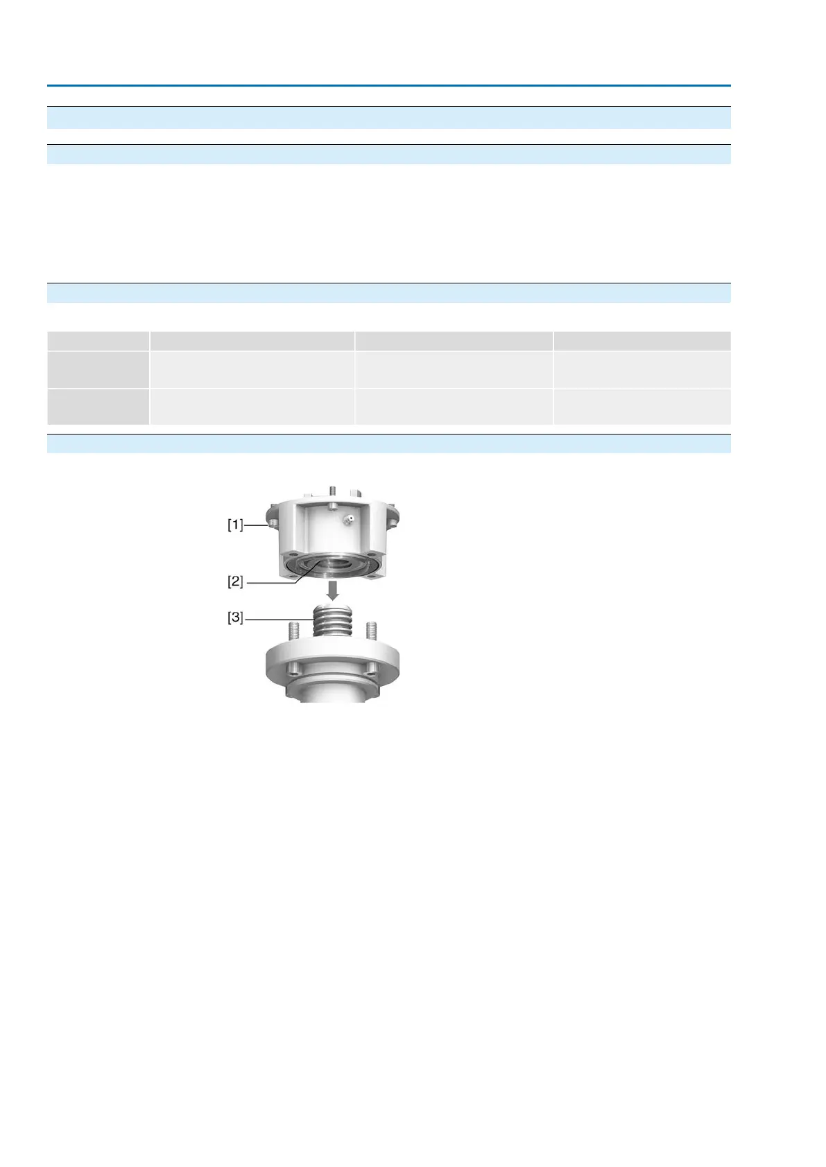
4.2.1. Design of output drive type A
Figure 8: Output drive type A
[1] Output mounting flange
[2] Stem nut with dog coupling
[3] Valve stem
Output mounting flange [1] with axial bearing stem nut [2] form one unit.Torque is
transmitted to valve stem [3] via stem nut [2].
To adapt the actuators to available output drive types A with flanges F10 and F14
(year of manufacture 2009 and earlier), an adapter is required.The adapter can be
ordered from AUMA.
16
SAEx 07.2 – SAEx 16.2 / SAREx 07.2 – SAREx 16.2 Control unit: electronic (MWG)
Assembly ACExC 01.2 Non-Intrusive Profinet