4.4.2. Multi-turn actuator with output drive type A: mount
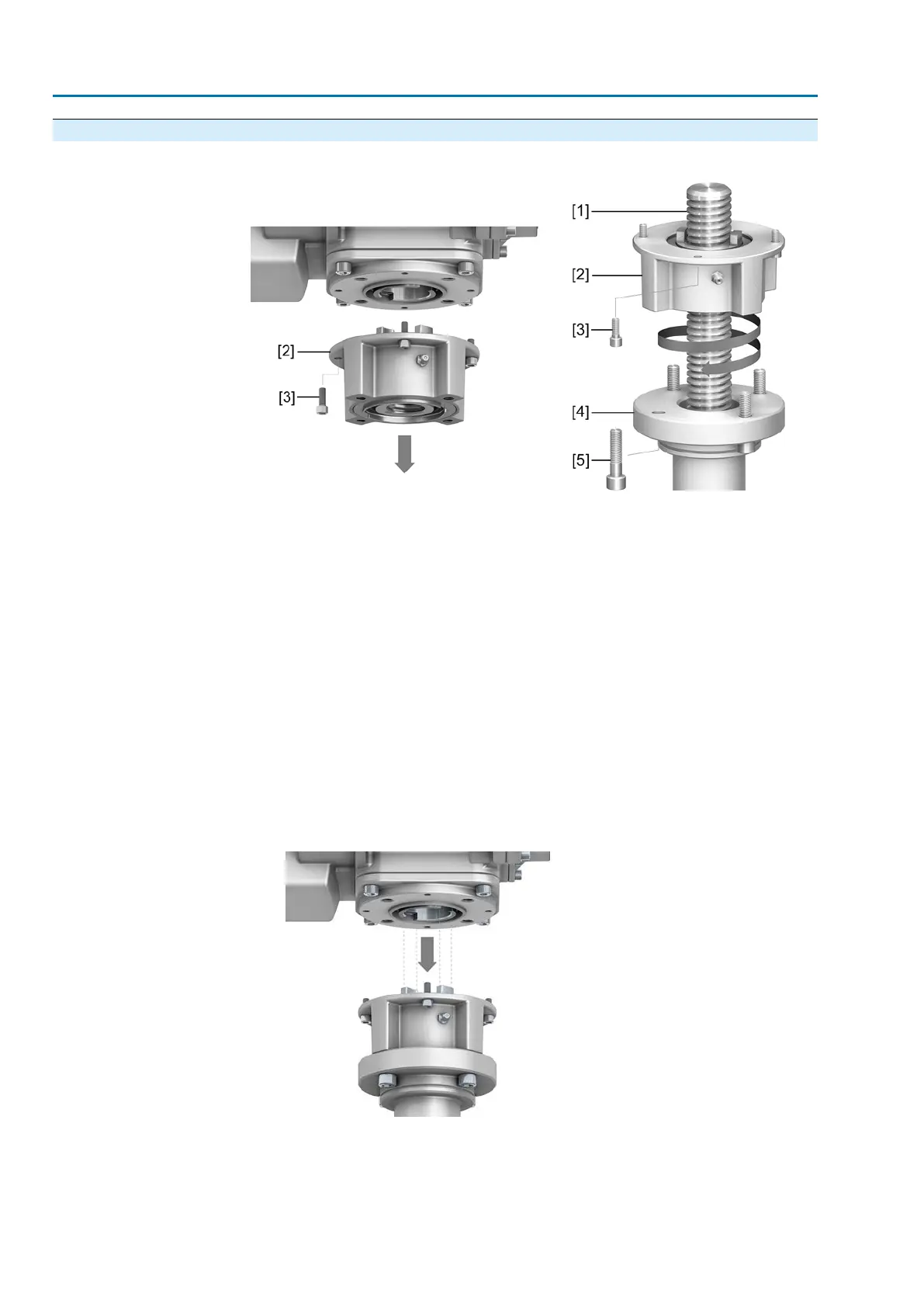
Figure 12: Assembly of output drive type A
[1] Valve stem
[2] Output drive type A
[3] Screws to actuator
[4] Valve flange
[5] Screws to output drive
Procedure
1. If output drive type A is already mounted to the multi-turn actuator: Loosen
screws [3] and remove output drive type A [2].
2. Apply a small quantity of grease to the valve stem [1].
3. Place output drive type A on valve stem and turn until it is flush on the valve
flange.
4. Turn output drive type A until alignment of the fixing holes.
5. Fasten screws [5] between valve and output drive type A without completely
tightening them.
6. Fit multi-turn actuator on the valve stem so that the stem nut dogs engage into
the output drive sleeve.
Figure 13:
➥
The flanges are flush with each other if properly engaged.
7. Adjust multi-turn actuator until alignment of the fixing holes.
8. Fasten multi-turn actuator with screws [3].
20
SAEx 07.2 – SAEx 16.2 / SAREx 07.2 – SAREx 16.2 Control unit: electronic (MWG)
Assembly ACExC 01.2 Non-Intrusive Profinet