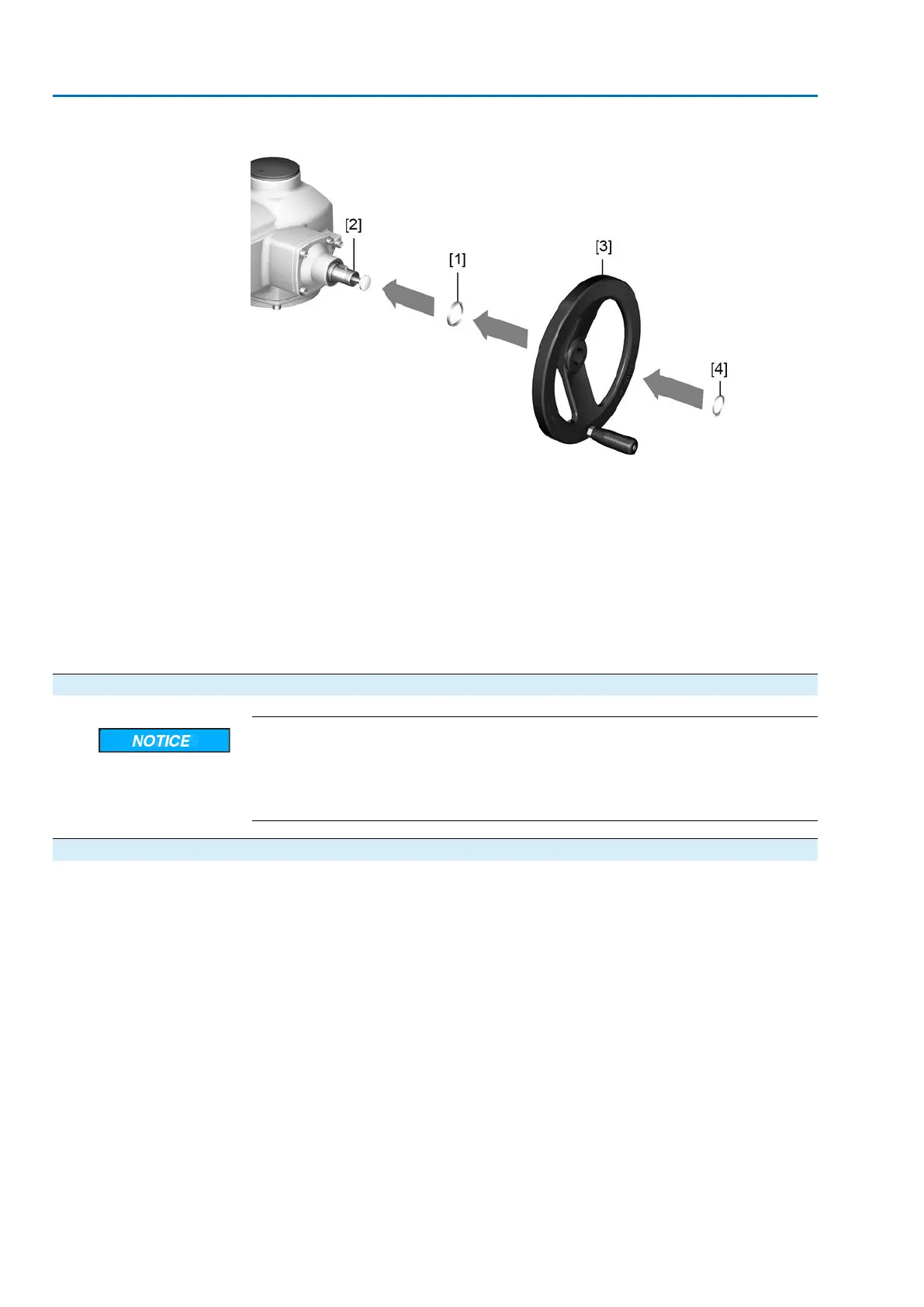
Figure 10: Handwheel
[1] Spacer
[2] Input shaft
[3] Handwheel
[4] Retaining ring
1. If required, fit spacer [1] on input shaft [2].
2. Slip handwheel [3] onto input shaft.
3. Secure handwheel [3] with retaining ring [4].
Information: The retaining ring [4] (together with these operation instructions)
is stored in a weatherproof bag, which is attached to the device prior to delivery.
4.4. Actuator: mount to valve
Corrosion due to damage to paint finish and condensation!
→
Touch up damage to paint finish after work on the device.
→
After mounting, connect the device immediately to electrical mains to ensure
that heater minimises condensation.
4.4.1. Stem nut for output drive type A: finish machining
This working step is only required if stem nut is supplied unbored or with pilot bore.
Information For exact product version, please refer to the order-related technical data sheet or
the AUMA Assistant App.
18
SAEx 07.2 – SAEx 16.2 / SAREx 07.2 – SAREx 16.2 Control unit: electronic (MWG)
Assembly ACExC 01.2 Non-Intrusive Profinet