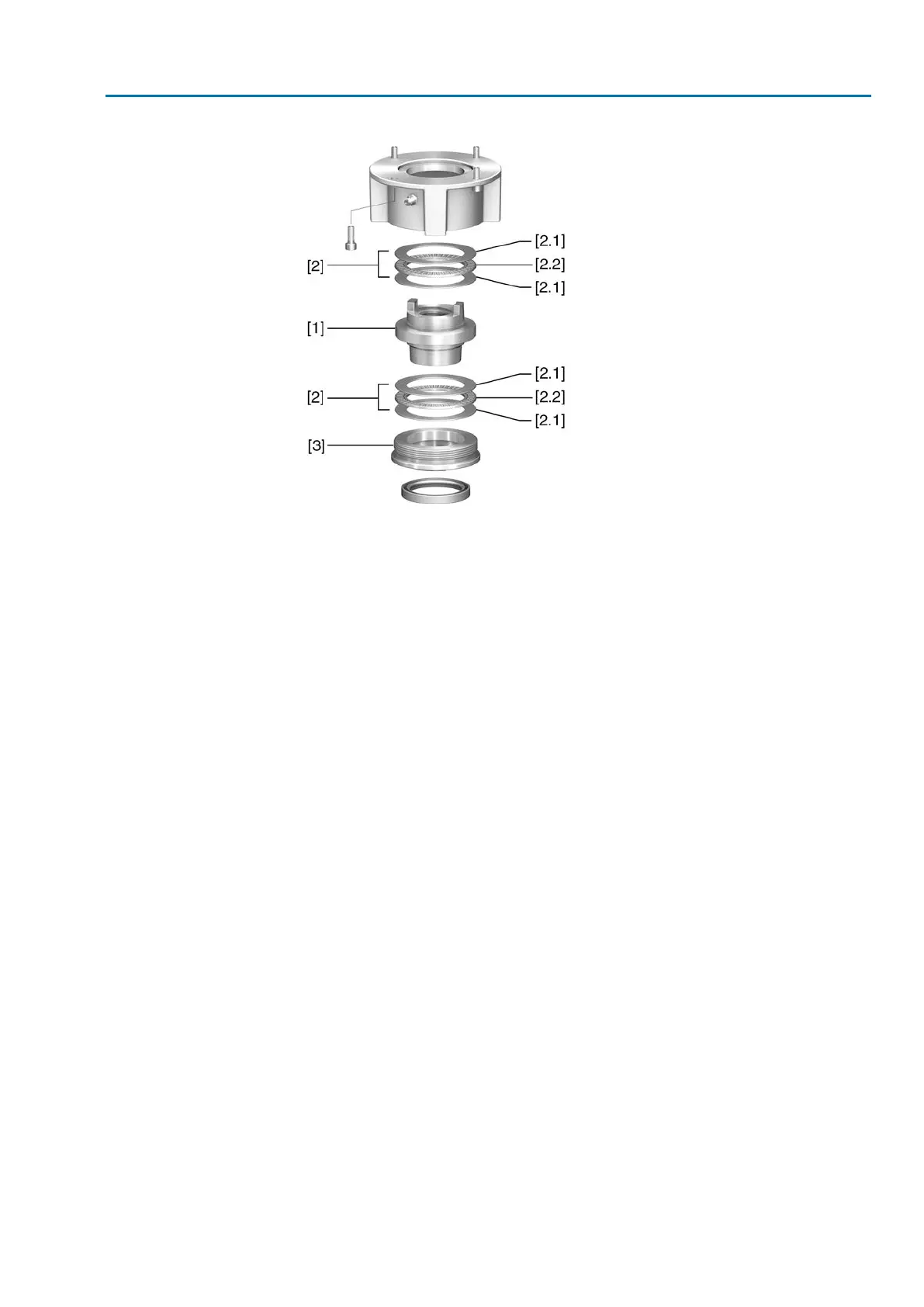
Figure 11: Output drive type A
[1] Stem nut
[2] Axial needle roller bearing
[2.1] Axial bearing washer
[2.2] Axial needle roller and cage assembly
[3] Spigot ring
Procedure
1. Remove spigot ring [3] from output drive.
2. Remove stem nut [1] together with axial needle roller bearings [2].
3. Remove axial bearing washers [2.1] and axial needle roller and cage assemblies
[2.2] from stem nut [1].
4. Drill and bore stem nut [1] and cut thread.
5. Clean the machined stem nut [1].
6. Apply sufficient Lithium soap EP multi-purpose grease to axial needle roller and
cage assemblies [2.2] and axial bearing washers [2.1], ensuring that all hollow
spaces are filled with grease.
7. Place greased axial needle roller and cage assemblies [2.2] and axial bearing
washers [2.1] onto stem nut [1].
8. Re-insert stem nut [1] with axial needle roller bearings [2] into output drive.
9. Screw in spigot ring [3] until it is firm against the shoulder.
19
SAEx 07.2 – SAEx 16.2 / SAREx 07.2 – SAREx 16.2 Control unit: electronic (MWG)
ACExC 01.2 Non-Intrusive Profinet Assembly