4.2.2. Design of output drive types B and E
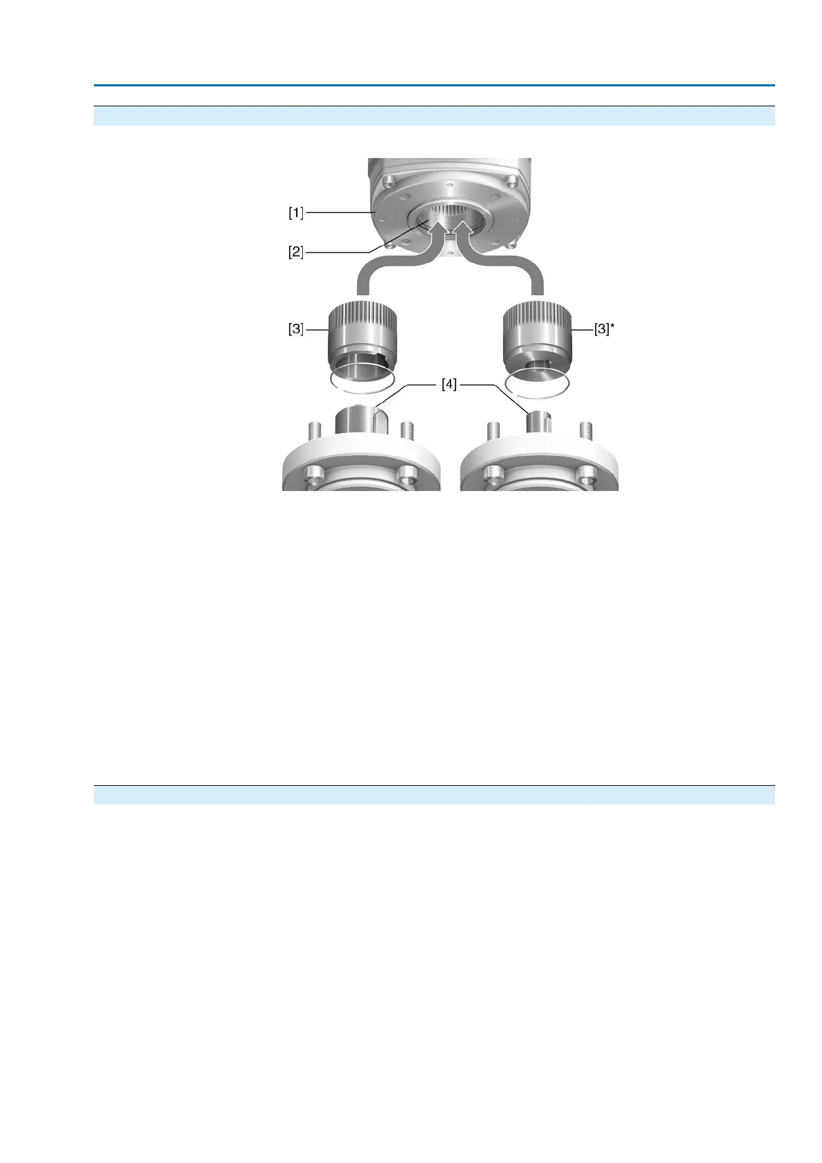
Figure 9: Output drive type B
[1] Flange multi-turn actuator (e.g. F07)
[2] Hollow shaft
[3] Output drive sleeve (illustration examples)
[3] B/B1/B2 and [3]* B3/B4/E, respectively with bore and keyway
[4] Gearbox/valve shaft with parallel key
Information
Spigot at valve flanges should be loose fit.
Connection between hollow shaft and valve or gearbox via output drive sleeve fixed
to the hollow shaft of the multi-turn actuator via retaining ring.
When exchanging the output drive sleeve, later retrofitting to a different output drive
type is possible
●
Output drive types B and E: Output drive sleeve with bore according to DIN
3210
●
Output drive types B1 – B4: Output drive sleeve with bore according to EN ISO
5210
4.3. Handwheel fitting
For transport reasons, handwheels with a diameter of 400 mm and larger are supplied
separately within the scope of delivery.
17
SAEx 07.2 – SAEx 16.2 / SAREx 07.2 – SAREx 16.2 Control unit: electronic (MWG)
ACExC 01.2 Non-Intrusive Profinet Assembly