Appendix D: Sizing an SR55 Soft Starter
Page D–3Stellar
®
SR55 Series Soft Starter User Manual – 1st Ed, Rev F – 09/18/2019
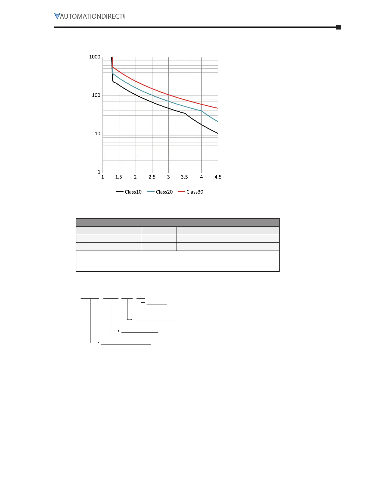
sR55 sofT sTARTeR oVeRloAd TRIp
Trip time ( seconds )
Multiple of Motor FLA
Motor overload 'cold' trip curves
(20°C ambient)
The SR55 soft starter provides motor
overload protection, which can be
configured through the touchscreen.
Overload trip settings are determined
by the Motor Current setting and the
Trip Class setting. Trip class choices
are class 10, class 20, and class 30.
The SR55 soft starters are protected
using full I
2
T motor overload with
memory.
sR55 INdex RATINGs
(per ieC 60947-4-2)
SR55 Index Ratings *
Model Number I
e
(A) Standard Operation AC-53a; X-Tx; F-S
SR55-017 to SR55-180 17 to 195 AC-53a: 3.5-17; 90-5
SR55-242 to SR55-477 242 to 500 AC-53a: 3.5-17; 90-3
* Index ratings AC-53a and AC-53b are specified by IEC standard # 60947-4-2.
IEC Index Ratings are comprised of Rated Operational Current (I
e
), Utilization
Category, Overload Current Profile (X-Tx), and Duty Cycle (F-S) or OFF-time.
index raTing example – sTandard operaTion
(aC-53a uTilizaTion CaTegory per ieC 60947-4-2)
17 to 195 - AC-53a: 3.5-17; 90-5
Duty Cycle (F-S)
90-5 = 90% duty cycle - 5 cycles/hr
[if multiple starts/hr are required, 90% D.C. requires off time ≥ 10% of previous run time]
Overload Current Profile (X-Tx)
3.5-17 = 3.5 times rated current (I
e
) for 17s
Utilization Category
AC-53a = controller semiconductors provide squirrel-cage motor Start, Run, and Stop control
Rated Operational Current (I
e
)
17 to 195 = controllers with Rated Operational Currents from 17A to 195A

 Loading...