Page 2–6 Stellar
®
SR55 Series Soft Starter User Manual – 1st Ed, Rev F – 09/18/2019
Chapter 2: Electrical Installation
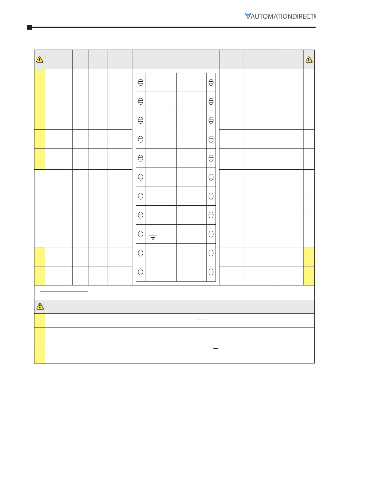
elecTRIcAl coNNecTIoNs
Required
Rating
Pro-
gram-
mable
Default
Descrip-
tion
Control Terminals
Descrip-
tion
Default
Pro-
gram-
mable
Required
Rating
#1
– – –
group
1 input
common
D1COM
D1-1I
D1-2I
D2COM
D2-1I
PTC+
PTC–
N
L
11
12
24
33
34
44
AO
AC OM
AI
110–230
VAC
0VDC
24VDC
group 1
relay
common
– – –
–
#1
24VDC or
110VAC or
230VAC +10%
-15%
yes
start /
stop
opto-
coupled
input
relay N/C fault yes
230VAC 1A
AC15;
30VDC 0.5A
Resistive
–
#1
24VDC or
110VAC or
230VAC +10%
-15%
yes none
opto-
coupled
input
relay N/O fault yes
230VAC 1A
AC15;
30VDC 0.5A
Resistive
–
#2
–
– –
group
2 input
common
group 2
relay
common
– –
–
–
#2
24VDC or
110VAC or
230VAC +10%
-15%
yes reset
opto-
coupled
input
relay N/O running yes
230VAC 1A
AC15;
30VDC 0.5A
Resistive
–
–
– – – not used relay N/O
end of
start
yes
230VAC 1A
AC15;
30VDC 0.5A
Resistive
–
–
3 x PTC in
series
(130°C)
– OFF thermistor
analog
output
0–10V yes
0 to 10V
10mA /
4-20mA
–
–
3 x PTC in
series
(130°C)
– OFF thermistor analog 0V – – 0V
–
–
– – –
signal
ground
analog
input
0–10V yes
0 to 10V
10mA /
4-20mA
–
#3
110VAC–
230VAC
+10% -15%
– –
control
supply
0V input – – 0V
#3
#3
110VAC–
230VAC
+10% -15%
– –
control
supply
24V input – –
24VDC
+10%
-15%
#3
* 24VDC Specification: 24VDC 60W; Residual ripple 100mV; Spikes/switching Peaks 240mV; Turn On/Off response;
No overshoot of V out; Overvoltage voltage protection output voltage must be clamped to <30Vdc
#1
The programmed digital input setting on D1COM, D1-1I, D1-2I must correspond to the voltage applied to these
terminals to avoid risk of damage to the equipment.
#2
The programmed digital input setting on D2COM, D2-1I must correspond to the voltage applied to these
terminals to avoid risk of damage to the equipment.
#3
The control supply can be 110 to 230VAC applied to the N, L terminals or 24VDC applied to the 0VDC, 24V input
terminals. The correct voltage as specified must only be applied to one of these supply inputs to avoid risk of
damage to the equipment.

 Loading...