Installation
Connecting Lines and Extensions
2-17
4. Connect the free end of each line cord to the
appropriate network interface jack
(see Figure 2-19).
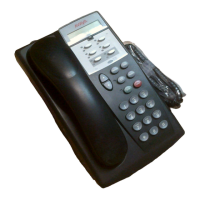
5. Test the lines by plugging a system telephone
into extension jack 10. Press the line button
for each outside line and listen for a dial tone.
6. Test the extensions by doing the following:
a. Plug a system telephone into the first
extension jack on each module.
b. Press the line button on the telephone for
each outside line and listen for a dial tone.
Figure 2-19. Connecting the Line Cord
to the Network Interface
Jack
7. Connect modular telephone cords to the
extension jacks, starting at the top extension
jack on the processor module
(see Figure 2-20). When that module is full,
move to the leftmost module. Fill each module
before moving on to the next module to the
right.
8. Route each cord through the wire manager on
the front of the module (see Figure 2-20).
9. Connect the free end of each modular
telephone cord to the modular wall jacks for
system extensions.
10. Gather the line and extension cords hanging
below the wire managers of the first two
modules, and twist-tie or wire-wrap them.
Repeat for the remaining cords. For the 5-slot
carrier, place each bundle of wires in the
indentations cut out of the bottom edge of the
carrier.
Figure 2-20. Connecting Cords to
Extension Jacks
555-
555-1347
555-1348
555-1349

 Loading...