Component Number Icon Description
You can also use the
systems management
software to cause the
indicators to flash to
identify a particular
system.
USB connectors (2) 5 The USB connector
button connects USB
2.0-compliant devices to
the system.
Bezel (panel cover) 6 The Bezel button
protects the front panel.
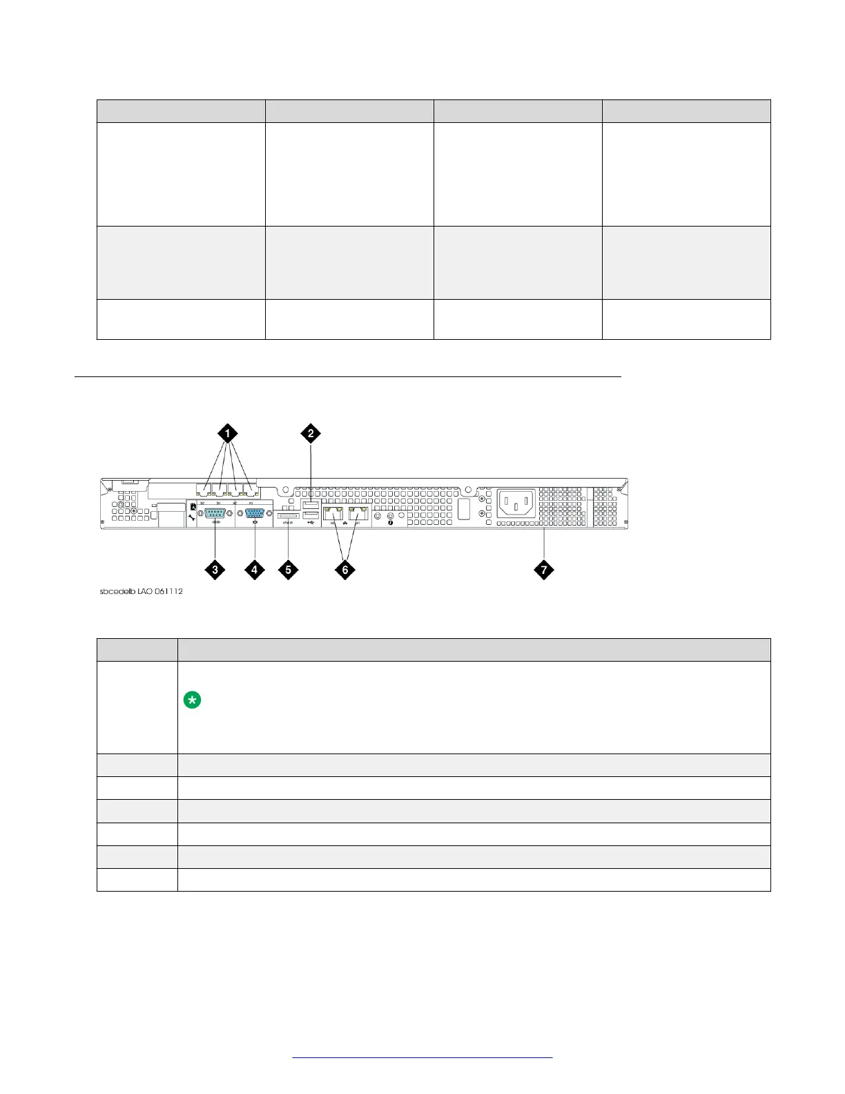
Rear panel (Dell R210–ii, Dell R210–ii XL)
Figure 2: Rear panel (Dell R210–ii, Dell R210–ii XL)
Number
Description
1 4X 100/1000 Ethernet Ports (PCI Card) used for data network
Note:
A blank plate is in the place of these ports on the EMS configuration of the Dell R210–ii
XL.
2 Two USB ports used for installation only
3 Serial Port used for Command Line Interface
4 VGA Port
5 E-SATA Port (not used)
6 Two 100/1000 Ethernet ports used for management interface
7 Non-Redundant Power Supply
Hardware overview
14 Deploying Avaya SBCE August 2015
Comments on this document? infodev@avaya.com