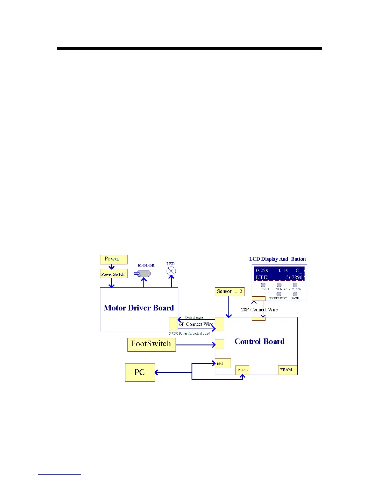
Electric Schematic Block
ST9500 electric system consists of Power, MCU Control, Motor Driver, LCD Display and Operation
Panel, Footswitch and Sensors, LED lighting etc.
ST9500 switching power provides the power supply for all the machine, the switching powers operates
on wide range of AC voltage 110 ~ 240VAC, 50/60Hz, you do not need any transformer if the industrial
power supply is within the range of 110 ~ 240VAC, 50/60Hz.
MCU controller consists of three MCU modules integrated in one control board. Among the three, one
MCU is to communicate with Motor Driver so as to control the cycle speed, rotating direction and stroke
of the stepping motor. The MCU is also used for panel display. The other two MCU are used for
network communication and control.
ST9500 Motor Driver receives instruction from MCU controller and drives the stepping motor to run
accordingly. LCD display is used to show to the user the current status of the machine. The operation
panel is used to change and save the settings for cycle speed, interval, mode etc. as mentioned in Chapter
3 Operating the Front Panel. Footswitch is used to give manual instruction so as to actuate the motor to
cycle or to stops it. Sensors are used for the machine to detect the top (home) position when the head
moves, MCU gets signals from these sensors and can judge if there’s a jamming occurs. LED lighting is
used for providing light to the operator.
The electric schematic block is shown below: