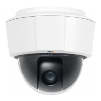
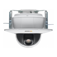
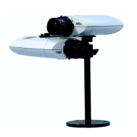
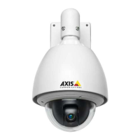
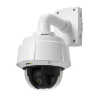
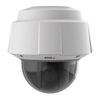
AXIS P5512 PTZ Dome Network Camera
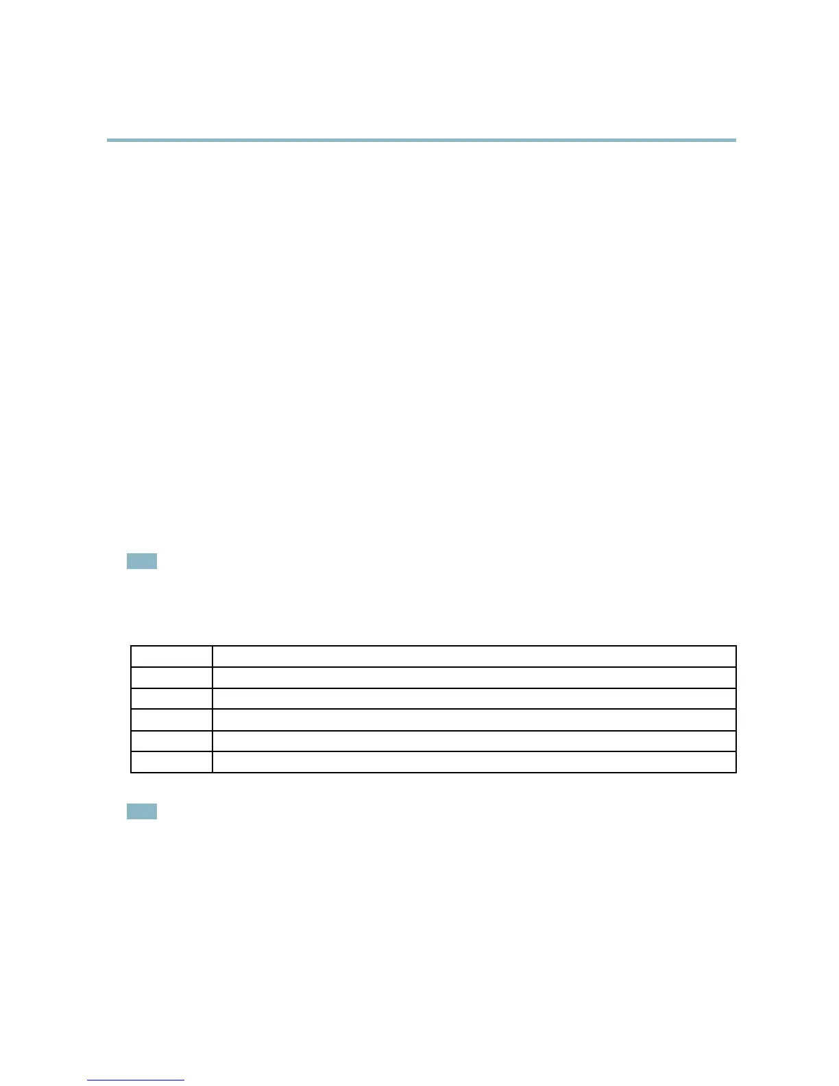
Hardware overview
Connectors
Network connector - RJ-45 Ethernet connector. Supports Power over Ethernet (PoE). A shielded network cable (STP) must be
used to protect the product against power surges.
Control button - The control button is used for:
• Connecting to a n AXIS Video Hosting System service, see page 37. To connect, press and hold the button until the
Status LED flashes green.
• Connecting to AXIS Internet Dynamic DNS Service, see page 38. To connect, press the button once.
• Resetting the product to factory default settings, see page 44.
Restart button - Press to restart the product.
Multi-connector - Terminal connector for connecting external equipment:
• Audio equipment
• Input/Output (I/O) devices
• AC/DC power supply
When connecting external equipment, a multi-connector cable (available from Axis) is required in order to maintain the product’s IP
rating, see Multi-Connector Cable ( sold separately), on page 45.
SD card slot - A standard or high-capacity SD card (not included) can be used for local recording with removable storage. For
instructions on how to insert and remove an SD card, please refer to the Installation Guide.
Note
Before removal, the SD card should be unmounted to prevent corruption of recordings. To unmount the SD card, go to Setup
>SystemOptions>Storage>SDCardand click Unmount.
LED indicators
Color
Indication
Unlit
Connection and normal operation
Amber
Steady during startup. Flashes
during firmware upgrade.
Amber/red Flashes amber/red if network connection is unavailable or lost.
Red Flashes red for firmware upgrade failure.
Green Shows steady green for 10 seconds for normal operation after restart.
Note
•Th
e Status LED can be configured to be unlit during normal operation, or to flash only when the product is accessed. To
configure, go to Setup > System Options > LED Settings. Se e the online help for more informa tion.
5