2-10
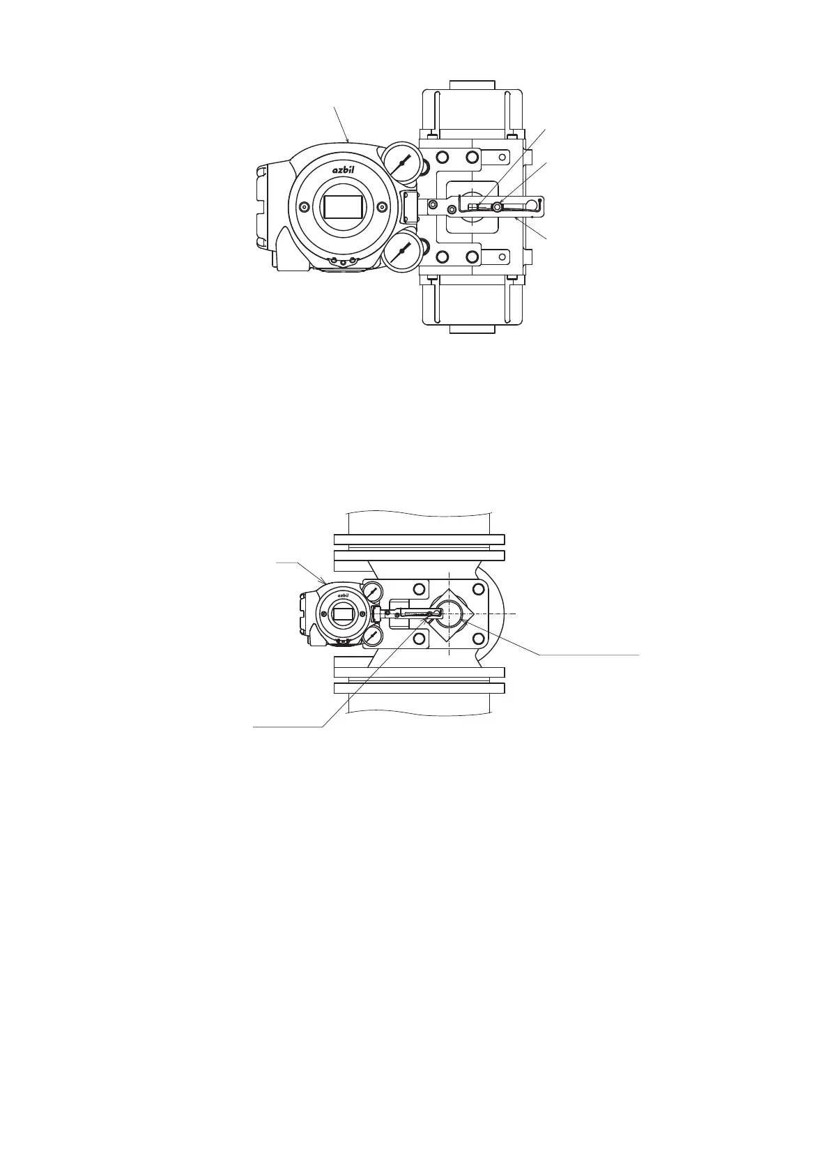
Feedback lever
Feedback pin
AVP
Figure 2-9 Connection of the Rotary Cylinder to the Feedback Pin and Feedback
Lever
- When the rotary cylinder is large and the lever is assembled so that the feedback pin
is positioned between the 700 Series and the shaft of the rotary cylinder as shown
in the figure below, select Rotary (sub)/90° (for 90°) or Rotary (sub)/other (for angles
other than 90°) as the Actuator Type according to the rotation angle.
Feedback pin
AVP
Shaft of rotary cylinder
Figure 2-10 Feedback Pin and Feedback Lever Connection for Rotary Cylinder (Large
Cylinder)
5) Maintenance space behind the device
The device has a nozzle flapper mechanism in the back of the main unit. When cleaning
the flapper, you must remove the pilot relay cover secured to the back with three screws.
Design the clamp and feedback mechanism to ensure maintenance space for cleaning.

 Loading...
