0024-9551 Revision 1
47
PCA
®
400 User Manual
IMPORTANT: When connecting the sensor assembly, it is important that the tubing
is free of crimps which could obstruct the ow of sample gases. (See Figure 5-5 for
proper sensor cap orientation.)
Fig. 5-4: Discard Shorting Springs
8. Reinstall the Analyzer’s Rear Cover
Using a Phillips-head screwdriver, return Battery & Component Doors to the rear of
the analyzer.
9. Allow Replacement Sensor to Stabilize
Allow the sensor which was just installed time to stabilize in the circuit before continuing
with this procedure. Stabilization time for all sensors (except for the NO sensor) is about
1-hour. The NO sensor baseline technically requires several days to stabilize, but should
be suciently stabilized for use in approximately 4-hours.
10. Turn ON the Analyzer
Press the Power Key and ensure that no sensor errors occur during the 60-second
warm-up.
6. Attach Sensor Cap Assembly
Attach the cap assembly to the replacement sensor by inserting the sensor into the gas
cup and twisting in a clockwise fashion.
7. Connect Replacement Sensor
Firmly press the sensor into the vacant position on the board and reconnect the sample
tubing to the gas cup.
4. Remove Sensor Cap Assembly
While holding the base of the sensor, rmly twist the gas cup in a counterclockwise fashion
and pull straight up to remove.
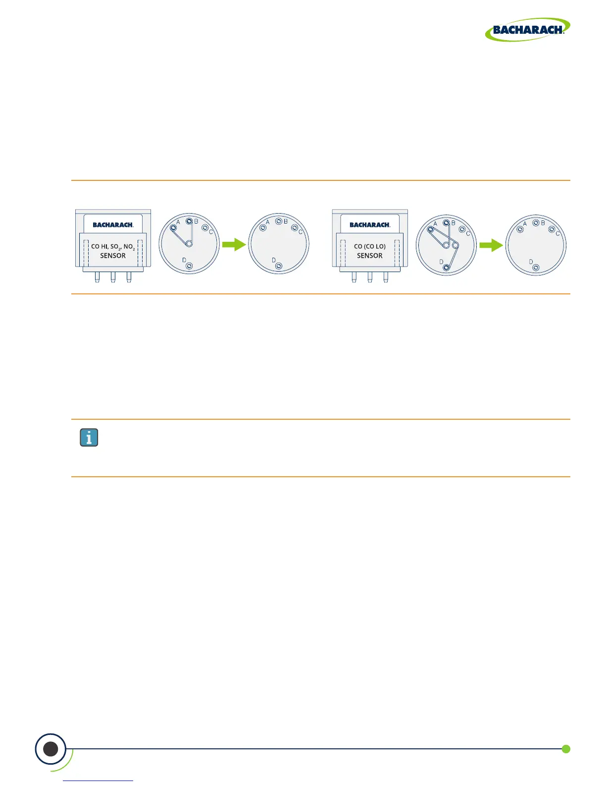
5. Remove Shorting Springs from Replacement Sensor
Remove the replacement sensor from its plastic canister / packaging. Note that the CO
LOW
,
CO
HIGH
, SO
2
and NO
2
sensors have a shorting spring installed between two of their pins.
Remove and discard this spring before installing the sensor