INTRODUCTION
REFERENCE DOCUMENTS
I-E96-508C 1 - 5
REFERENCE DOCUMENTS
Table 1-3 lists other Bailey documents containing information
relevant to the DC modular power system.
SPECIFICATIONS
Table 1-4 lists DC modular power system specifications.
24 VDC input field power module
48 VDC input field power module
IEPDF01
IEPDF02
24 VDC input system power module
48 VDC input system power module
IEPDS01
IEPDS02
DC power entry panel with redundant DC feed and
circuit breakers
IEPEP04
Power mounting unit
Rear mount
Front mount
IEPMU01
IEPMU02
NOTE
: The DC transfer module and bus monitor module have part numbers (refer to Table 7-1).
Table 1-2. Nomenclature
(continued)
Description Nomenclature
Table 1-3. Reference Documents
Number Document Title
I-E96-500 Site Planning and Preparation
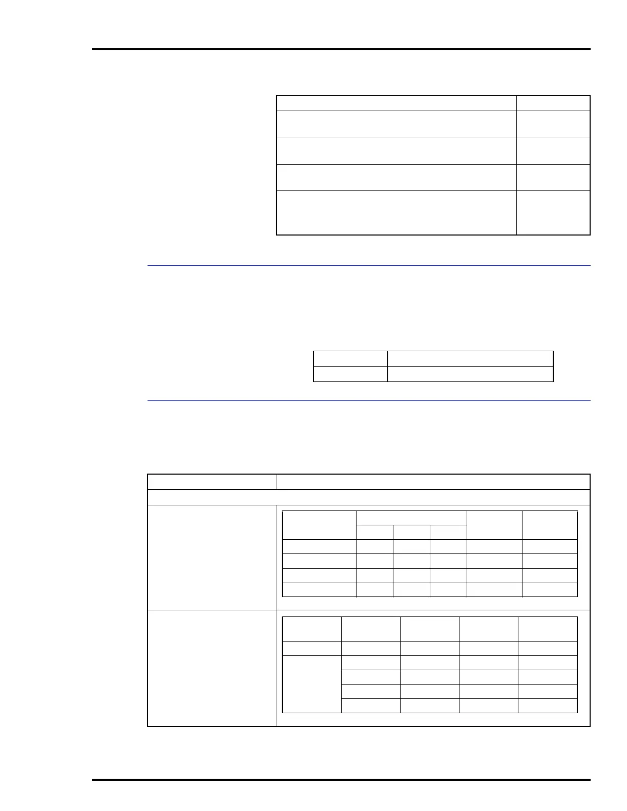
Table 1-4. Specifications
Property Characteristic/Value
IEPDS01/02, IEPDF01/02 Power Modules
Module input requirements
Module outputs
Module
Voltage (VDC)
Current (A)
Max
Power (W)
Nom
Min Nom Max
IEPDF01 212430 6.5 102
IEPDF02 424860 3.25 102
IEPDS01 212430 7.6 117
IEPDS02 424860 3.8 117
NOTE:
Inrush current increases from 0 A to steady state in 3 seconds typically.
Module
Voltage
(VDC)
Current
(A)
Power
(W)
Tolerance
(%)
IEPDF01/02 25.5 4.0 102.0 +6/-0
IEPDS01/02 5.1 10.0 51.0
±
3.0
-15.0 0.5 7.5
±
2.3
+15.0 0.5 7.5
±
2.3
25.5 4.0 102.0 +6/-0
NOTE
: Total 5 VDC and 24 VDC power output per module should not exceed 102 watts.