INSTALLATION
IEPEP04 POWER ENTRY PANEL WIRING
I-E96-508C 3 - 3
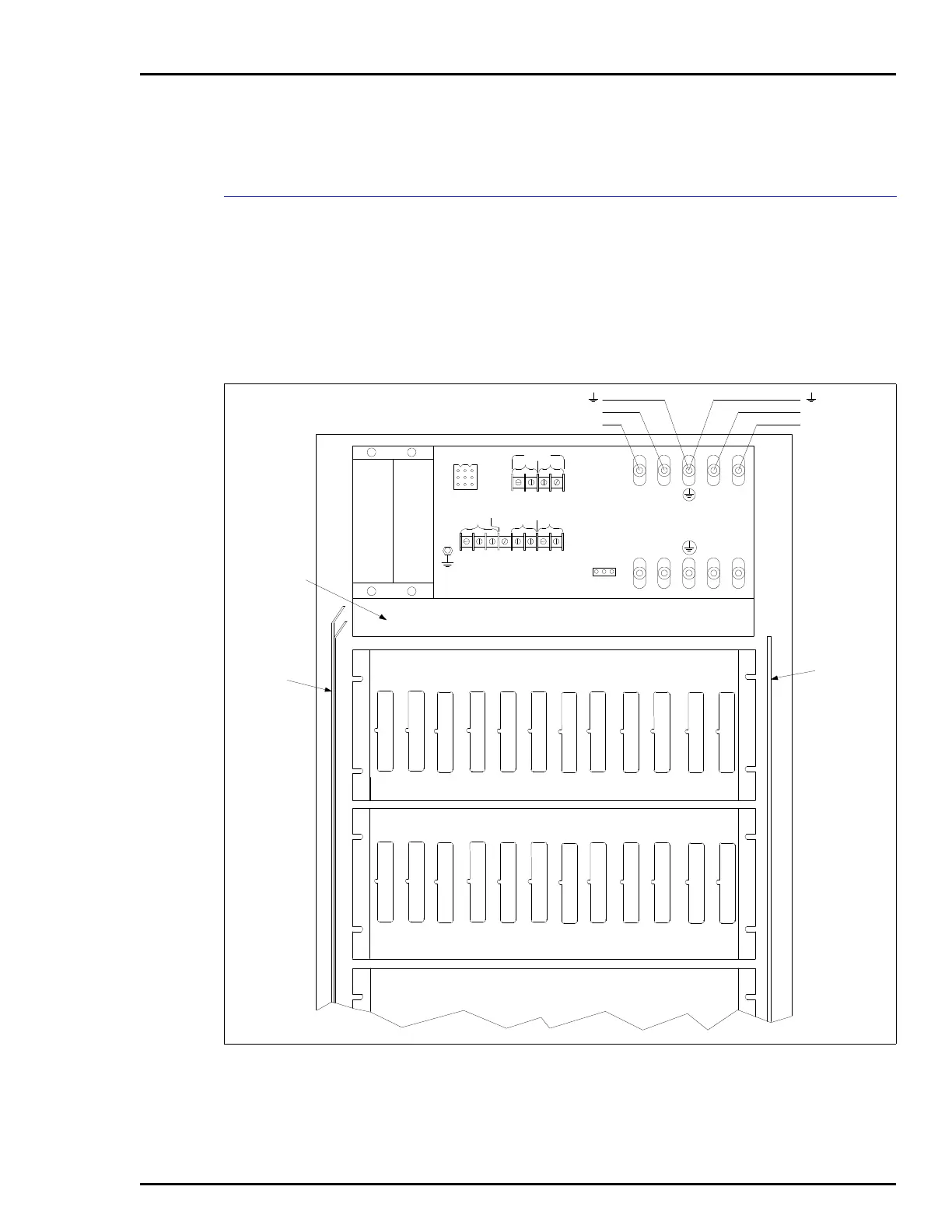
the power entry panel at the top, with the fan assembly placed
between the power entry panel and the module mounting
units. See Figure 3-1.
IEPEP04 POWER ENTRY PANEL WIRING
The appendices at the back of this manual show complete wir-
ing diagrams of the modular power system. Figures C-1 and
C-2 show the IEPEP04 system cabinet wiring diagram.
NOTE:
Plug your wrist strap ground cord into the WRIST STRAP
GND receptacle on the power entry panel when working with the
system.
Figure 3-1. System Cabinet (Rear View)
12345678
1234
I/O COM
+24 V
PM STAT
+15 V
-15 V
PFI
MCOM
J2
+-+-
AUX BUS
MONITOR
CH 1 CH 2
+-+-
BUS VOLT
PWR SYS
ALARMS
STATUS
OUT
STATUS IN
1MCOM2
N ASSEMBLY
GND
FAN OUT
DC
TRANSFER
BUS
MONITOR
TB9
TB8
TB10
TB11
TB12
OUT
OUT
L1 IN
L2 IN
TB3 TB4
TB5
TB6
TB7
INPUT POW
BUS BAR
STEM POWER
S BAR
TB1
POWER ENTRY PANEL
IEPEP04
TB2
24/48 VDC (+)
LINE 1 (-)
LINE 2
(-)
24/48 VDC (+)
+
+
+
+
-
-
-
-