DESCRIPTION AND OPERATION
POWER DISTRIBUTION
2 - 2 I-E96-508C
®
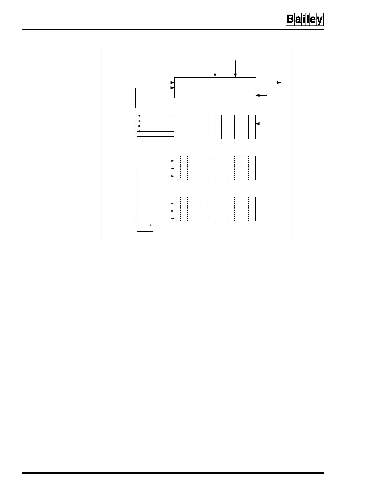
The input power bus bar distributes DC power from the power
entry panel (PEP) to the module mounting unit (MMU) back-
planes. The bus bar has quick connect tabs to connect cables
from the power entry panel and the module mounting unit.
IECAB03 cabinets have power mounting units (PMU) and do
not have input power bus bars. A cable distributes power
directly from the PEP panel to the PMU card cage (see
Figure 2-2).
The eight-layer system power bus bar distributes regulated DC
voltages, power supply status and power fail interrupt (PFI) sig-
nals. This bus bar also has quick connect tabs.
High-current, multi-conductor flat cables connect regulated
voltage outputs and status signals from the MMU backplane to
the system power bus bar. A cable from the power entry panel
to the system power bus bar allows the system to monitor bus
voltages and status signals. Extra tabs are available at the bot-
tom of the system power bus bar for connecting 24 VDC I/O
power to field termination units or to other cabinets. Tabs are
also available to connect DC common and I/O common to the
system common bus bar at the bottom of the cabinet.
Figure 2-2. Block Diagram of Modular Power System with
Power Mounting Unit
FAN
LINE 1 LINE 2
ALARM CONTACT
OUTPUT
POWER SUPPLY STATUS
BUS MONITOR
DETECTION
POINTS
EXTERNAL SUPPLY AND
CUSTOMER STATUS
+24 VDC FOR I/O
+24 VDC COMMON
+5 VDC
-15 VDC
+15 VDC
+5 VDC
+24 VDC
-15 VDC
+15 VDC
TP25245B
POWER ENTRY PANEL
PDS PDS PDS
PDF
PDF
24/48 VDC
24/48 VDC
+5 VDC
-15 VDC
+15 VDC
ANY INFI 90 MODULES
ANY INFI 90 MODULES
PDS PDS PDS PDS PDS PDS PDS
SYSTEM
POWER
BUS BAR
PMU
MMU
MMU