INSTALLATION
IEPMU01/02 POWER MOUNTING UNIT INSTALLATION
I-E96-508C 3 - 13
7. Slide heat shrink tubing over PMU connection (see Figure
3-7). Insure that connections are properly covered, then use
heat gun to shrink the tubing into place.
8. Attach one end of the 6 AWG wire assembly (part number
6632885_48) to the fifth conductive strip (from the top) on the
left side of the PMU.
9. Attach the other end of 6 AWG wire assembly to the system
power bus bar I/O COM tab located at the top of the bus bar.
10. Slide heat shrink tubing over PMU connection (see
Figure 3-8). Insure that connections are properly covered, then
use heat gun to shrink the tubing into place.
11. On the left side of the PMU at the sixth conductive strip
(from the top) attach one end of 6 AWG wire assembly (part
number 6632885_48).
12. Attach the other end of 6 AWG wire assembly to system
power bus bar 24 VDC tab located at the top of the bus bar.
13. Slide heat shrink tubing over PMU connection (see Figure
3-8). Insure that connections are properly covered, then use
heat gun to shrink the tubing into place.
NOTE:
If system bus bar (Bailey part number 1948506_8) is revi-
sion C or older, it will not have tabs at the top for 24 VDC connec-
tions. Use the 10 AWG wires supplied with the PMU to connect to
the system power bus bar fastons identified as 24 V and I/O COM.
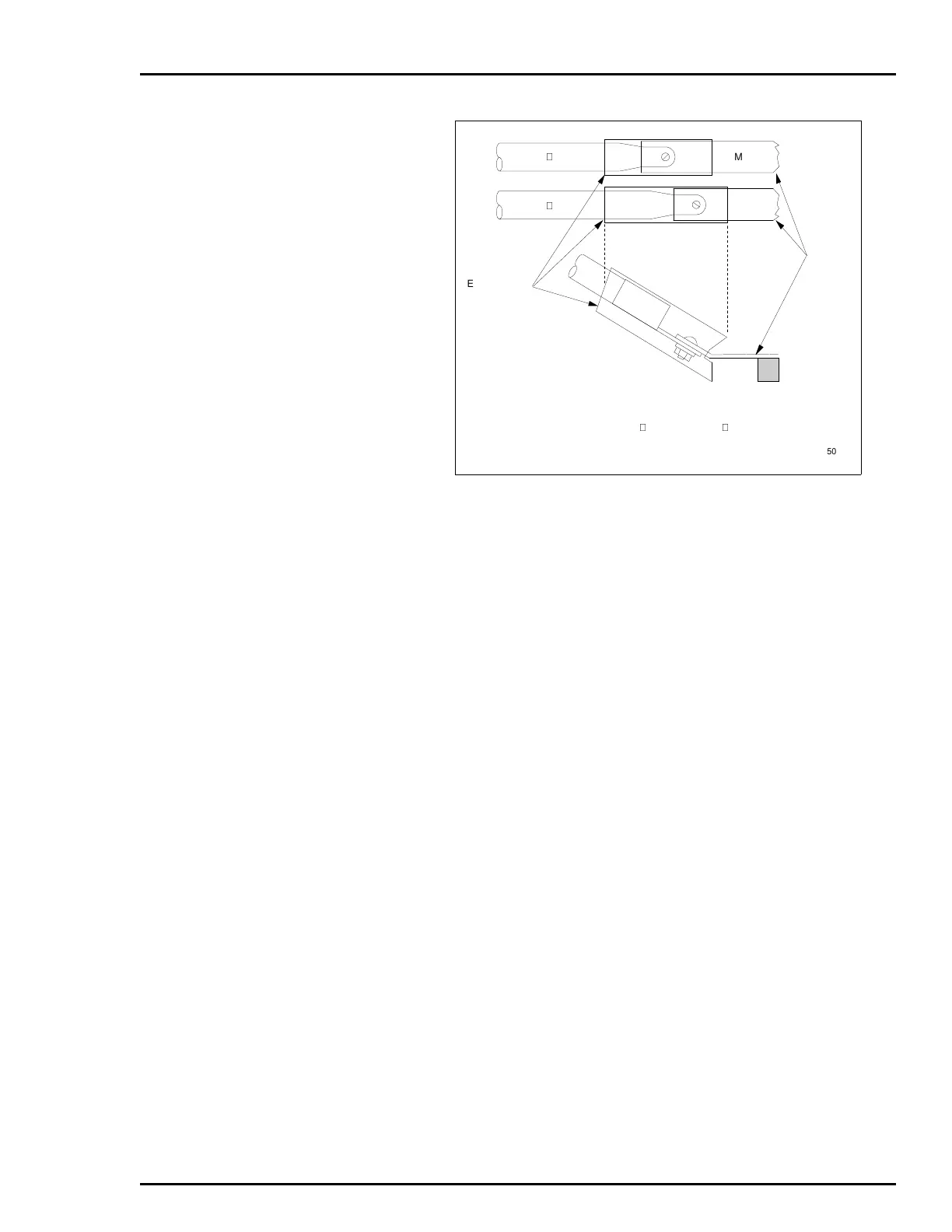
Figure 3-7. Heat Shrink Tubing for 5 VDC Connection
6632285 47
MCOM
6632285 45
HEAT SHRINK
TUBING
PMU
BUS BAR
STANDOFF
+5 V
NOTE: AFTER JUMPER CONNECTION IS MADE, SLIDE HEAT SHRINK
TUBING SUPPLIED WITH P/N 6632285 45 AND 6632285 47 OVER
CONNECTION UNTIL CONNECTION IS COVERED COMPLETELY AND
SHRINK INTO PLACE WITH HEAT GUN.
TP50376B