INSTALLATION
IEPEP04 POWER ENTRY PANEL WIRING
I-E96-508C 3 - 9
Fan Assembly
The fan assembly (Figure 3-1) mounts directly beneath the
power entry panel and above the first module mounting unit.
Attach the fan power cable to the FANOUT connector on the
power entry panel.
Power Modules
Power modules (Figure 3-5) mount directly in the module
mounting unit (MMU). Any slot except the rightmost (slot 12)
can be used. Install the modules as explained in Steps 1
through 5 and as shown in Figure 3-6. This installation
scheme provides the best heat dissipation and power distribu-
Figure 3-4. Bus Monitor Module Board Layout
S1
J1
P3
TP50301B
CR12
CR17
ON
1234
J2
J3
J4
J5
J6
J7
1
2
3
4
1
2
3
4
1
2
3
J8
1
2
3
1
2
3
1
2
3
1
2
3
4
1
2
3
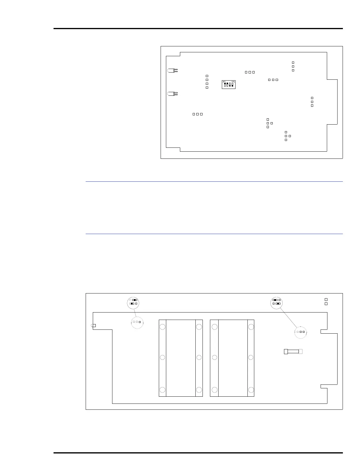
Figure 3-5. Power Module Board Layout
A
B
J3
CR9
F1
A
B
J2
TP25136B
A
B
J3 POSITION A - FOR +5, +24, +15, -15 V MONITORING
J3 POSITION B - TO DISABLE ±15 VDC MONITORING
A
B
J2 POSITION B FOR IEPDF0
J2 POSITION A FOR IEPDS0