DESCRIPTION AND OPERATION
POWER MODULE STATUS
2 - 6 I-E96-508C
®
circuitry determines if any status line is bad. If any status is
bad, the bus monitor module generates a low-true output sig-
nal to the communication system hardware, which is the bus
interface module (BIM) for plant loop systems and the network
interface slave (NIS) for INFI-NET systems.
Bus Voltage Status
The BMM module logically ANDs the DC bus voltage status
lines and outputs the result to an isolated customer alarm out-
put. If any bus output voltage signal falls out of specification, a
bus voltage alarm is generated.
POWER MODULE STATUS
The power modules generate their own status signals. These
signals travel through the system power bus bar to the bus
monitor module. The bus monitor module then combines this
signal with the other status signals. If it or any other signal is
bad, a power system status alarm is generated.
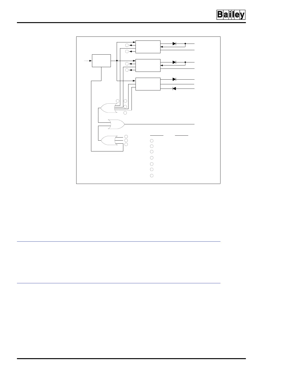
Figure 2-4. Block Diagram, PDS Module Converter and
Status Circuitry
DC/DC
DC/DC
DC/DC
6
7
6
7
1
2
3
4
5
6
7
I/O POWER 24 V
I/O COMMON
+5 V
SYSTEM COMMON
SYSTEM COMMON
+15 V
-15 V
STATUS
ALARM
DC
SOFTSTART
CIRCUIT
TP25132B
5
6
7
1
2
3
4
LEGEND
+24 V OVERPOWER
+5 V SOURCE OVERPOWER
-15 V UNDER/OVERVOLTAGE
+15 V UNDER/OVERVOLTAGE
BLOWN DC INPUT FUSE
OVERTEMP SHUTDOWN
OVERVOLTAGE SHUTDOWN