INSTALLATION
IEPEP04 POWER ENTRY PANEL WIRING
3 - 8 I-E96-508C
®
Table 3-3 for jumper definitions. See Figure 3-4 for the bus
monitor module circuit board layout.
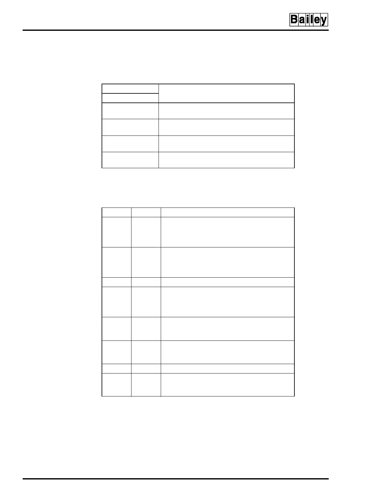
Table 3-2. Bus Monitor Module Switch (S1) Setting
Pole
Function
1234
0
1
Monitor 5, 15 and ±15 VDC enabled
Monitor 5, 15 and ±15 VDC disabled
0
1
Monitor system 24 VDC enabled
Monitor system 24 VDC disabled
0
1
Monitor external power supply CH1 enabled
Monitor external power supply CH1 disabled
0
1
Monitor external power supply CH2 enabled
Monitor external power supply CH2 disabled
NOTE
: 0 = CLOSED (ON), 1 = OPEN (OFF).
1. Unused monitor inputs must be disabled. Do not enable all switches at once. Doing so will cause
a bad status signal. Figure 3-4 shows the factory settings of switch S1.
Table 3-3. Bus Monitor Module Jumper Settings
Jumper Setting
1
Function
J1
1-2
2-4
2-3
Auxiliary bus monitor channel 1:
Selects 24 VDC external power
Selects 48 VDC external power
Selects 125 VDC external power
J2
1-2
2-4
2-3
Auxiliary bus monitor channel 2:
Selects 24 VDC external power
Selects 48 VDC external power
Selects 125 VDC external power
J3 2-3 Not used, must install jumper in this position
J4
1-2
2-3
3-4
Auxiliary status input 1:
Normally open (NO) status input
Normally closed (NC) status input
PFI input (NO)
J5
1-2
2-3
Auxiliary status input 2:
Normally open (NO) status input
Normally closed (NC) status input
J6
2
1-2
2-3
Input power isolation:
Do not isolate input power
Isolate input power
J7 2-3 Not used, must install jumper in this position
J8
2
1-2
2-3
Input/output common isolation:
Isolate input common from output common
Do not isolate input common from output common
NOTES
:
1. Short pins with a jumper to enable function.
2. Jumpers J8 and J6 must be set so that they correspond (i.e.,both set for isolation or no isolation).