INSTALLATION
IEPEP04 POWER ENTRY PANEL WIRING
I-E96-508C 3 - 7
3. Slide the module into the slot until its faceplate is flush
with the power entry panel.
4. Turn the 2 thumbscrews 1/2-turn to lock the module in
place.
Bus Monitor Module
Before mounting the bus monitor module, set jumpers J1
through J7. Refer to Table 3-2 for switch settings. Refer to
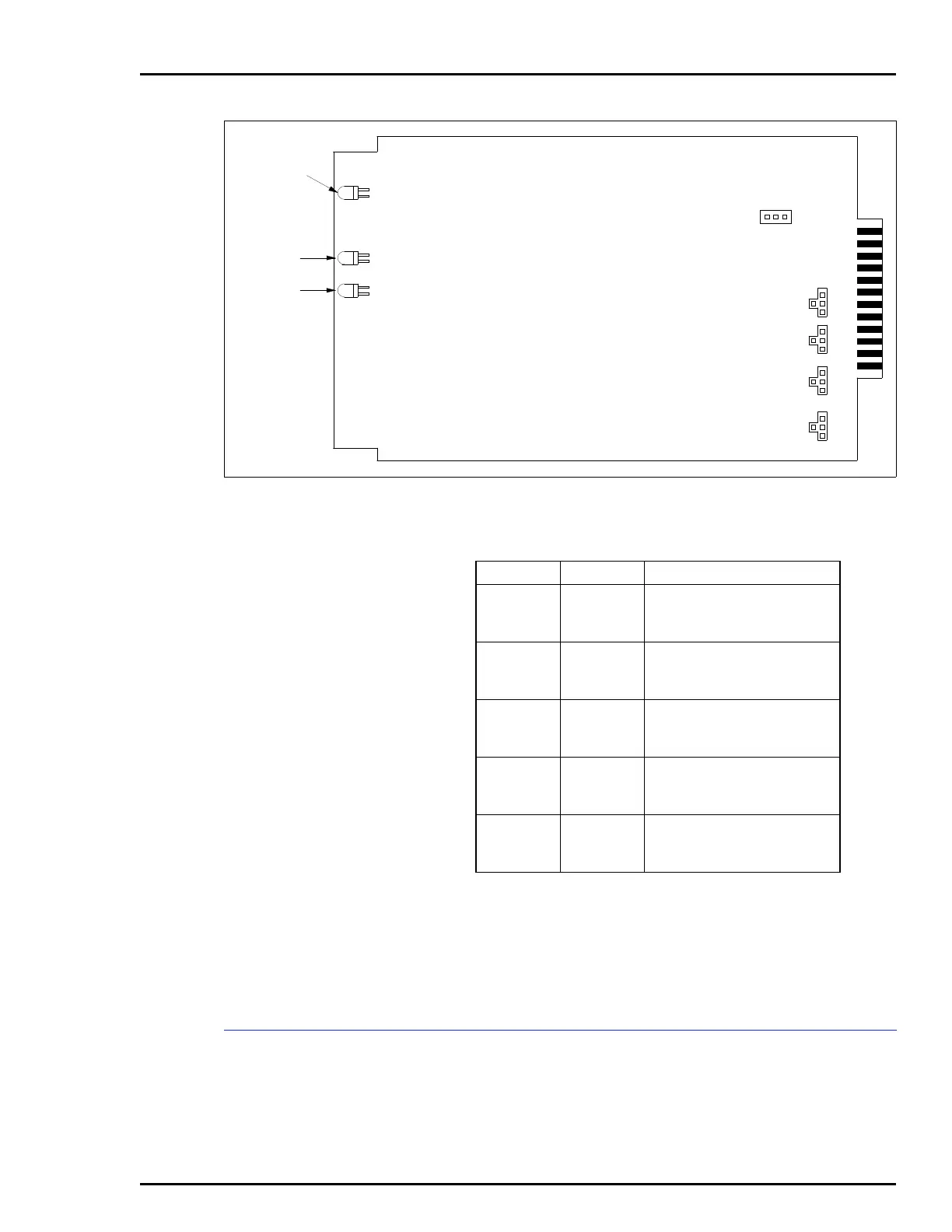
Figure 3-3. DC Transfer Module Board Layout
TP25141A
J13
123
125V
48V
24V
125V
48V
24V
J1
J2
J3
J4
CR1
CR2
CR3
RED/GREEN
STATUS
LINE 1
LINE 2
3
4
1
2
3
4
1
2
3
4
1
2
3
4
1
2
Table 3-1. DC Transfer Module Jumper Settings
Jumper Setting Function
J1
1-4
2-4
Line 1 input:
24 VDC high detect
48 VDC high detect
J2
1-4
2-4
Line 1 input:
24 VDC low detect
48 VDC low detect
J3
1-4
2-4
Line 2 input:
24 VDC high detect
48 VDC high detect
J4
1-4
2-4
Line 2 input:
24 VDC low detect
48 VDC low detect
J13
2-3
1-2
Input power source:
24 VDC
48 VDC
NOTE
: Short pins with a jumper to enable function.