INSTALLATION
IEPEP04 POWER ENTRY PANEL WIRING
3 - 10 I-E96-508C
®
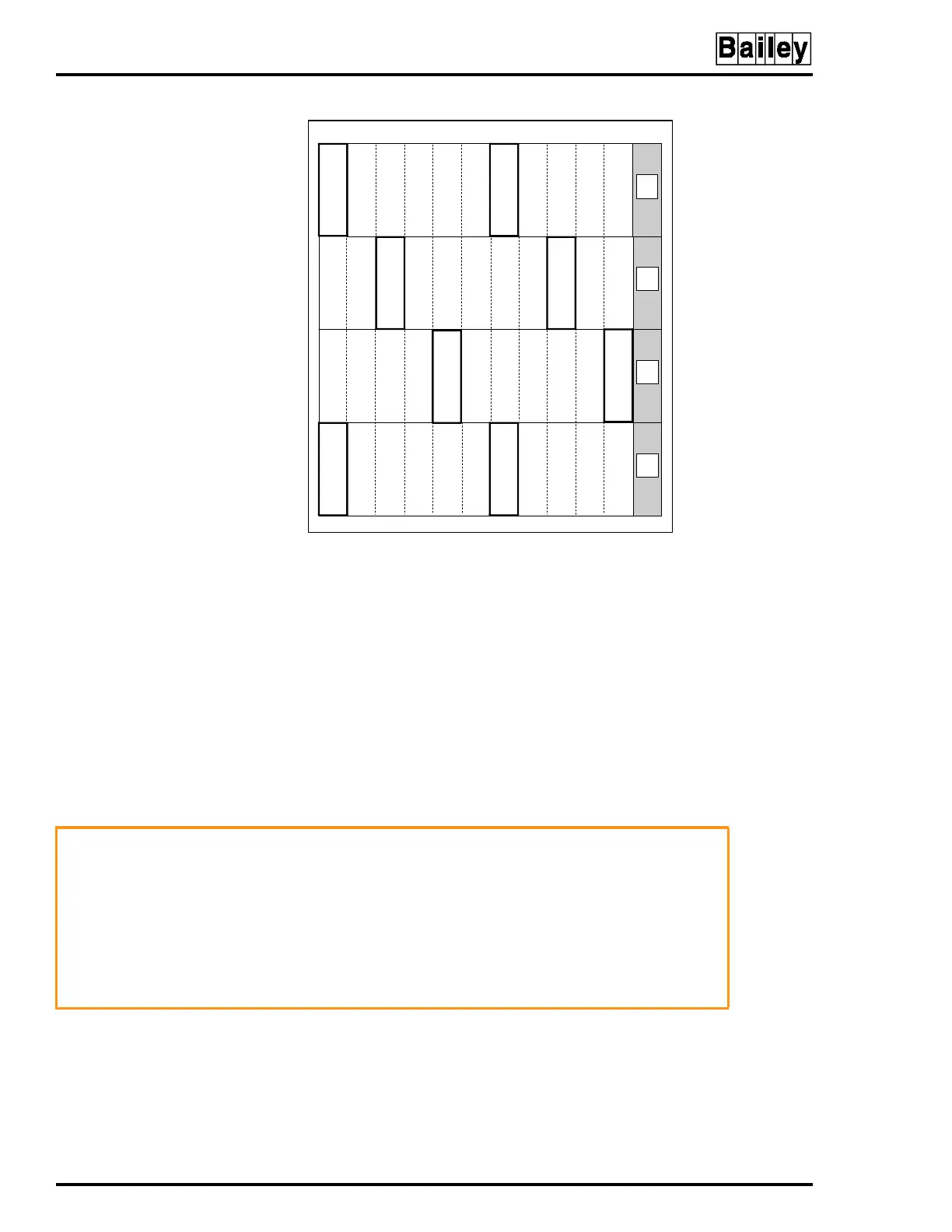
tion. For optimum heat dissipation and power distribution, do
not exceed more than two IEPDS01 and IEPDS02 modules in
any module mounting unit. Install at least one IEPDS01 and
IEPDS02 module in the module mounting unit with the largest
load (i.e., an MMU card cage containing several multi-function
processor modules).
NOTE:
The power mounting unit can hold a maximum of 12 power
modules mounted side by side. However the total five VDC current
load on the power mounting unit cannot exceed 100 amps. The total
24 VDC current load on the power mounting unit cannot exceed 60
amps.
Before handling the power modules:
•
Verify that all devices connected to the module are properly
grounded before using them.
Figure 3-6. Recommended Power Module Layout
TP25135A
PDS PDS
1
2
3
4
56
7
89
10 11
12
PDSPDS
PDS PDS
PDSPDS
NOT
USED
NOT
USED
NOT
USED
NOT
USED
WARNING
Do not remove the plastic covers on the module mounting unit
backplane. These covers protect against accidental contact
with DC voltage. Severe or fatal shock could result.
AVERTISSEMENT
Ne retirez pas les couvercles de plastique situés sur le pan-
neau arrière du châssis de montage des modules. Ces couver-
cles constituent une protection contre les contacts accidentels
avec la tension c.c., qui risquent de provoquer des chocs
sérieux et même mortels.