QUICK REFERENCE MATERIAL
INTRODUCTION
A - 2 I-E96-508C
®
DC transfer
module (cont.)
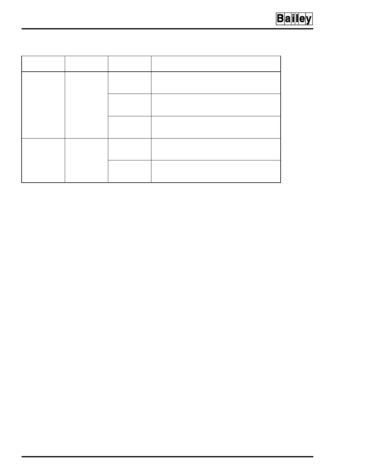
J3
1-4
2-4
Input power, line 2:
24 VDC high detect
48 VDC high detect
J4
1-4
2-4
Input power, line 2:
24 VDC low detect
48 VDC low detect
J13
1-2
2-3
Input power source:
48 VDC
24 VDC
All power
modules
J2
A
B
Enable 5 VDC, ±15 VDC, and 24 VDC monitoring
Disable ±15 VDC monitoring
J3
A
B
IEPDS01/02 power module IEPDF01/02 power
module
NOTE:
1. Jumpers J6 and J8 must have corresponding settings (i.e., both set for isolation or no isolation).
Table A-1. Switch and Jumper Setting Reference Guide
(continued)
Device
Dipswitch
Settings
Jumper
Position
Function