MODULE POWER REQUIREMENTS
SIZING THE MODULAR POWER SYSTEM
B - 6 I-E96-508C
Q1 = number of PDS power modules needed to meet 5 and
24 VDC current requirements
Q2 = number of PDS power modules needed to meet
+15 VDC current requirements
Q3 = number of PDS power modules needed to meet
-15 VDC current requirements
QS = the largest value of Q1, Q2 or Q3
QS(N) = number of PDS power modules needed to power the
system
QS(N+1) = number of modules needed for N+1 redundancy,
add 1 to the value of QS(N)
The following equations should be used when sizing systems
having only PDS supplies.
If B ≥ A/5 then Q1 = (A/20) + (B/4)
If B < A/5 then Q1 = A/10
Q2 = C/0.5
Q3 = D/0.5
QS = largest value of Q1, Q2 and Q3
QS(N) = value of QS rounded to the next highest integer =
number of PDS power modules required
QS(N+1) = if using N+1 redundancy, add 1 to the value of
QS(N)
NOTE:
The tables in Appendix D contain calculated values of Q1, Q2
and Q3 for various load combinations. These tables enable you to
size the modular power system without doing the sizing calculations.
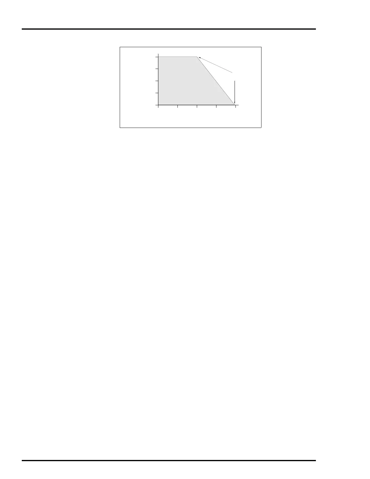
Figure B-1. Power Output of One IEPDS01/02 Module
OUTPUT CURRENT OF
25.5 VDC OUTPUT (AMPS)
OUTPUT
CURRENT OF
5.1 VDC
OUTPUT
(AMPS)
102 W
OUTPUT MAX.
MAX. POWER
OUTPUT OF PDS
TP25244A
1
0
2.5
5.0
7.5
10.0
234