19 © Banner Engineering Corp. www.bannerengineering.com
SENSOR PROGRAMMING
3.2.7. Output (out2)
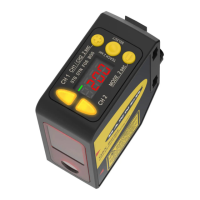
The number that follows out on the display indicates which channel is selected.
The Output 2 menu is available in Channel 2. Use this menu to select light operate (LO) or dark operate (DO). The default output configuration
is light operate. To switch between light operate and dark operate, select the desired menu option.
• Lo—Light operate
• do—Dark operate
3.2.8. Adaptive Tracking (trc2)
In adaptive tracking mode, the laser intensity changes to compensate for a loss in excess gain - normally caused by a dirty lens.
When operating in Dual Mode, the Adaptive Tracking Algorithm adjusts the switching thresholds (distance and intensity) around a taught refer-
ence surface. Adaptive tracking adjusts for small variations in the reference surface to maintain a consistent 100P (100%) on the display and to
ensure reliable detection. The Adaptive Tracking menu is only available when Teach Ch2 is set to Dual Mode.
Adjustment of the thresholds only occurs when the reference surface is visible to the senor (that is, no target is present). The Adaptive Tracking
Algorithm can reduce or eliminate the need to periodically re-teach the sensor as environmental conditions change around the sensor.
Enable or disable the Adaptive Tracking Algorithm from the sensor menu. The appropriate speed depends on the application. This menu is avail-
able only if Dual Mode is selected. For Channel 2, the output must be set to light operate or dark operate.
• HS—High-Speed Adaptive Tracking On
• on—Adaptive Tracking On
• oFF—Adaptive Tracking Off (default)
OFF disables the Adaptive Tracking Algorithm—Prevents the sensor from adjusting the thresholds around the taught reference surface while
the sensor is in dual mode. The sensor will not adapt to or learn any target. Environmental changes may cause the displayed value to deviate
from 100P (100%) over time. A periodic re-teach of the reference surface may be required to restore the displayed value to 100P if this is
important to the application.
There are some cases in which disabling adaptive tracking is useful. For example, disable adaptive tracking if the target passes very slowly
through the sensing beam, if the target might stop while partially blocking the beam, and if the environmental conditions are stable.
ON enables the Adaptive Tracking Algorithm at the standard speed—Recommended for many applications detecting low contrast targets.
Standard adaptive tracking adjusts the thresholds around slowly changing background and environmental conditions. It adjusts the sensor for
stable detection when the environment changes due to gradual dust accumulation, machine vibration, or ambient temperature changes which
influence the signal from the reference surface. Standard adaptive tracking will not easily adapt to or learn slow moving, low contrast targets (for
example, clear targets entering and exiting the beam over approximately 2 seconds).
HS enables the Adaptive Tracking Algorithm at high speed—Optional adaptive tracking setting used with dual mode. Use high speed adap-
tive tracking when the signal from the reference surface changes quickly due to unstable environmental conditions and high contrast and
high-speed targets are being detected. High speed adaptive tracking adjusts the sensor for stable detection in challenging environmental condi-
tions such as dust accumulation, machine vibration, ambient temperature changes, or a non-stable reference surface (for example, a running
Figure 15: Slope—Voltage Sourcing Models
The analog voltage output tracks slightly beyond the upper window limit (up to 10.2 V)
Figure 16: Slope—Current-Sourcing Models
The analog current output tracks slightly beyond each window limit (from 3.8 mA to 20.2 mA)
0
Near
Window
Far
Window
10
Analog Output (V dc)
Positive
Slope
Target Position
4
Near
Window
Far
Window
20
Target Position
Analog Output (mA)
Positive
Slope
 Loading...

