5 © Banner Engineering Corp. www.bannerengineering.com
INSTALLATION
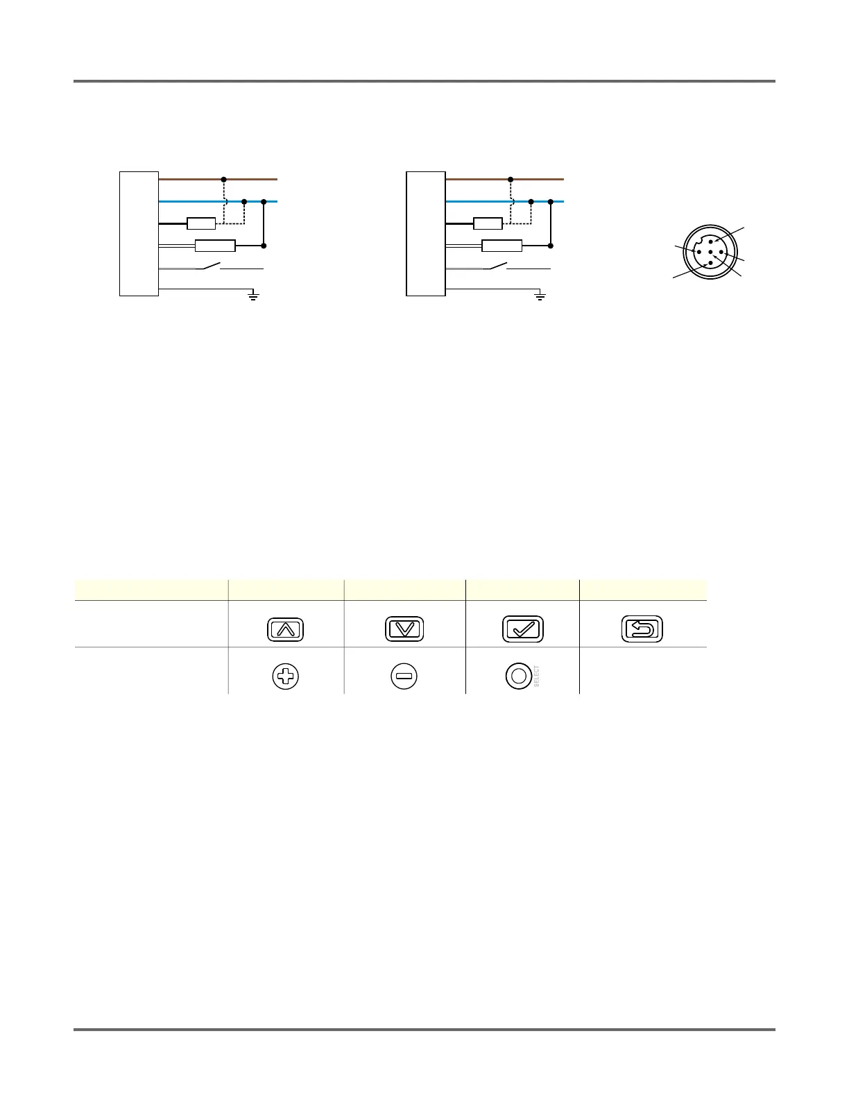
2.3. Wiring Diagrams
2.4. Cleaning and Maintenance
Clean the sensor when soiled and use with care.
Handle the sensor with care during installation and operation. Sensor windows soiled by fingerprints, dust, water, oil, etc. may create stray light
that may degrade the peak performance of the sensor. Blow the window clear using filtered, compressed air, then clean as necessary using only
water and a lint-free cloth.
2.5. Button Map from RSD1 to Sensor
The sensor may be optionally connected to the Banner RSD1 remote display accessory. Refer to this table for the RSD1 button association with
your sensor.
Figure 7: Wiring diagram for 4-20mA Analog Figure 8: Wiring diagram for 0-10V Analog
Table 1:Button association between the RSD1 and the Q4X/Q5X sensors
Device Up Button Down Button Enter Button Escape Button
RSD1
Q4X and Q5X N/A
shield
+
12–30 V DC
D_Out/IO-Link
A_Out
Input
–
Load
* Push-Pull output. User-configurable PNP/NPN setting.
4-20 mA
bu (3)
bn (1)
wh (2)
bk (4)
gy (5)
*
*
PNP
NPN
shield
+
12–30 V DC
D_Out/IO-Link
A_Out
Input
–
Load
* Push-Pull output. User-configurable PNP/NPN setting.
0-10 V
bu (3)
bn (1)
wh (2)
bk (4)
gy (5)
*
*
PNP
NPN

 Loading...