14 P/N 133487
Banner Engineering Corp. • Minneapolis, U.S.A.
www.bannerengineering.com • Tel: 763.544.3164
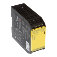
SC22-3 Safety Controller
Instruction Manual
Components and Specifications
Power
24V dc, ± 20%
0.4 A (controller only),
5.9 A (all outputs ON @ full rated load)
The Controller should be connected only to a SELV or PELV power supply.
Safety and Non-Safety
Inputs (22 terminals)
Input ON threshold: > 15V dc (guaranteed on), 30V dc max.
Input OFF threshold: < 5V dc (guaranteed off with any 1 fault), –3V dc min.
Input ON current: 8 mA typical @ 24Vdc, > 2 mA (guaranteed with 1 fault)
50 mA peak contact cleaning current @ 24V dc
Sourcing current: 30 mA minimum continuous (3V dc max. drop)
Input lead resistance: 300 Ω max. (150 Ω per lead)
Safety Outputs
(6 terminals, 3 redundant
outputs)
Rated output current: 0.75 A max. @ 24V dc (1.0V dc max. drop)
Output OFF threshold: 0.9V dc typical (1.2V dc max. guaranteed with 1 fault)
Output leakage current: 50 µA max. with open 0V
Load: 0.1 µF max., 1 H max., 10 Ω max. per lead
Status Outputs
(10 terminals)
Rated output current: 0.5A @ 24V dc (individual), 1.0 A @ 24V dc (total of all outputs)
O1 to O8 (General Purpose) Output OFF voltage: < 0.5V dc (no load)
O9 and O10 (Monitored Mute Lamp) Output OFF voltage: Internal 94 KΩ pull up to V supply
Output ON/OFF threshold: 15V dc +/-4V dc @ 24V dc supply
NOTE: For O9 and O10, if a short circuit or other fault condition causes the output to drop below this
threshold while the output is ON, a lockout will occur. If an open circuit or other fault condition
causes the output to rise above this threshold while the output is OFF, a lockout will occur.
Response and
Reaction Times
Response time (ON to OFF): 10 ms max. (with standard 6 ms debounce; this can increase if debounce
time increases. Refer to the configuration summary for actual response time.)
Reaction time (OFF to ON): 400 ms max. (with manual reset option)
Reaction time (OFF to ON): 400 ms max. plus input debounce time (auto reset)
Onboard LCD
Information Display—
Password Requirements
Password is not required:
Run mode (I/O status)
Fault (I/O fault detection and remedial steps)
Review configuration parameters (I/O properties
and terminals)
Password is required:
Configuration mode (create/modify/confirm/
download configurations)
Environmental Rating
NEMA 1 (IEC IP20), for use inside NEMA 3 (IEC IP54) or better enclosure
Operating Conditions
Temperature range: 0° to +55° C (+32° to 131° F)
Mechanical Stress
Shock: 15g for 11 milliseconds, half sine, 18 shocks total (per IEC 61131-2)
Bump: 10g for 16 milliseconds, 6000 cycles total (per IEC 61496-1)
Vibration: 3.5mm occasional / 1.75mm continuous @ 5Hz to 9Hz, 1.0g occasional and 0.5g continuous @
9Hz to 150Hz: (per IEC 61131-2) and 0.35 mm single amplitude / 0.70 mm peak-to-peak @ 10 to
55Hz (per IEC 61496-1), all @ 10 sweep cycles per axis
EMC
Meets or exceeds all EMC requirements in IEC 61131-2, IEC 61496-1 (Type 4), and IEC 62061 Annex E,
Table E.1 (increased immunity levels)
Removable Terminals
Screw terminals
Wire sizes: 16, 18, 20, 22 or 24 AWG (0.20 – 1.31 mm
2
)
Wire strip length: 5.00 mm (0.197")
Tightening torque: 0.23 Nm (2 in. lbs) nominal
Tightening torque: 0.34 Nm (3.0 in. lbs) maximum
Clamp terminals
Wire size: 16, 18, 20, 22, or 24 AWG (0.20 – 1.31 mm
2
)
Wire strip length: 9.00 mm (0.35")
Important: The clamp terminals are designed for 1 wire only. If more than 1 wire is connected to
a terminal, a wire could loosen or become completely disconnected from the terminal,
causing a short.
2.2 Specifications
 Loading...
