P/N 133487 61
Banner Engineering Corp. • Minneapolis, U.S.A.
www.bannerengineering.com • Tel: 763.544.3164
SC22-3 Safety Controller
Instruction Manual
System Checkout Procedures
7.2 Commissioning Checkout Procedure
Before proceeding, verify that:
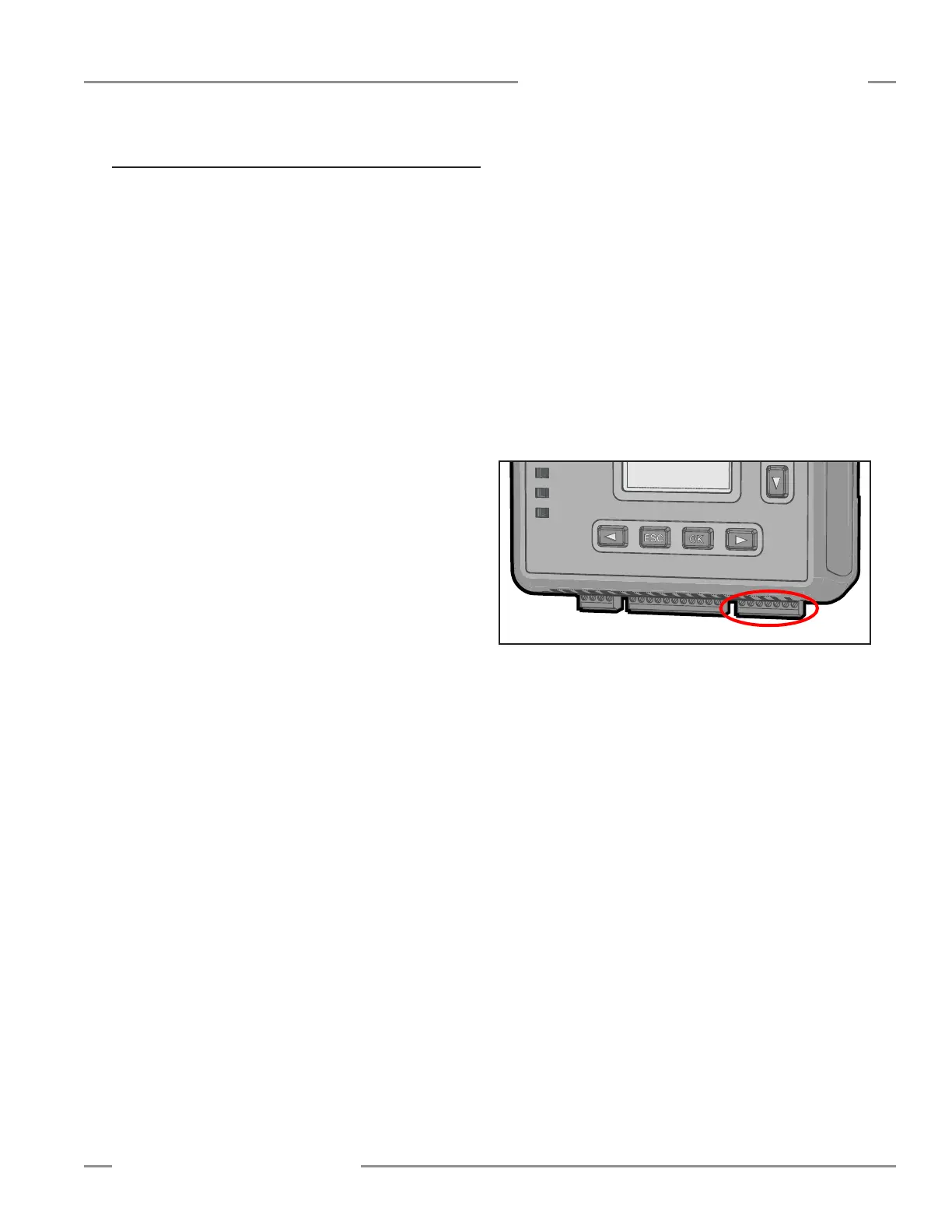
• The Safety Output terminal strip is NOT connected to the
SC22-3 Safety Controller; unplug the 7-pin connector so that
the safety outputs SO1 (A and B), SO2 (A and B) and SO3
(A and B) are not connected to the machine), and
• Power has been removed from the machine, and no power is
available to the machine controls or actuators.
Permanent connections will be made at a later point in this
checkout.
Verifying System Operation
The commissioning checkout procedure must be performed by a
Qualified Person, as defined in the glossary of this manual (see
Warning, page 60). It must be performed only after configuring
the Controller and after properly installing and configuring the
safety systems and safeguarding devices connected to its inputs
(per Appendix A and the appropriate standards).
The commissioning checkout procedure is performed on two
occasions:
• When the Controller is first installed, to ensure proper
installation and
• Whenever any maintenance or modification is performed
on the System or on the machinery being guarded by the
System, to ensure continued proper Controller function. (See
Section 7.1 for a schedule of required checkouts.)
For the initial part of the commissioning checkout, the
Controller and associated safety systems must be checked
without power being available to the guarded machine. Final
interface connections to the guarded machine cannot take place
until these systems have been checked out.
□ Verify that:
• The safety output leads are isolated — not shorted
together, and not shorted to power or ground;
• If used, external device monitoring (EDM) connections
have been connected to +24V dc via the N.C. monitoring
contacts of the device(s) connected to the safety outputs, as
described in Section 3.6 and Figures 3.12—3.15.
• The proper Controller configuration file for your application
has been installed into the SC22-3; and
• All connections have been made according to the appropriate
sections and comply with NEC and local wiring codes.
This procedure will allow the Controller and the associated safety
systems to be checked out, by themselves, before permanent
connections are made to the guarded machine.
Figure 7-1. Safety output terminal block
SC22-3
Safety Controller
Power
Status
Tx/Rx
SO1
SO2
SO3