P/N 133487 35
Banner Engineering Corp. • Minneapolis, U.S.A.
www.bannerengineering.com • Tel: 763.544.3164
SC22-3 Safety Controller
Instruction Manual
Configuration — PC Interface
4.2 Configuration Tools
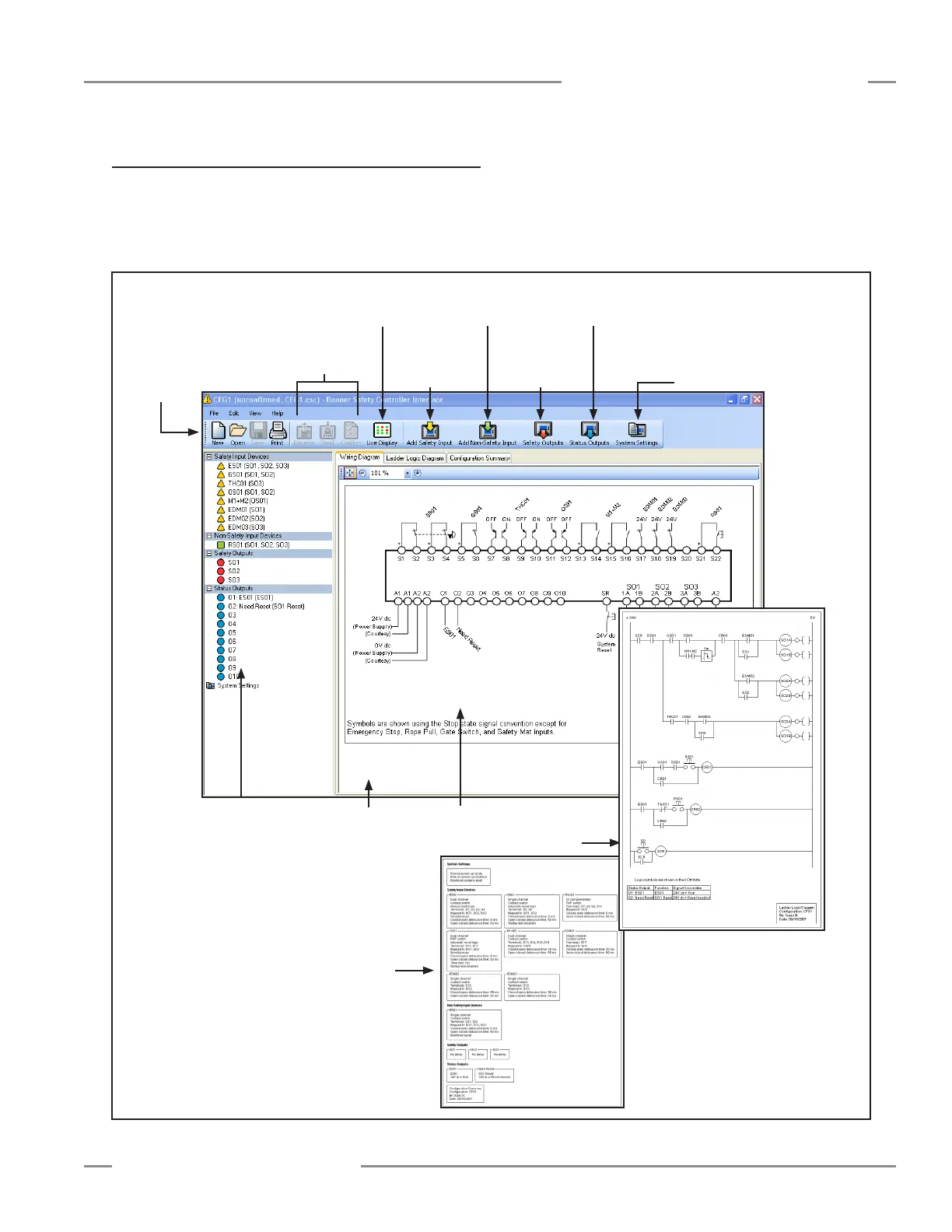
The PC Interface screen (shown below) has the tool bar on top
of the work area for creating and managing configuration files.
The Live Display button permits the PCI to display real time Run
mode data from a working Controller over a USB connection.
Figure 4-1. PCI Main screen components
Send, receive and confirm buttons
appear in color when a powered
Controller or programming tool is
connected to the PC
Access the
live display
I/O Properties
Double-click to access
property settings.
Tool Bar
Add a safety
input to the
configuration
Add a non-safety input to
the configuration
Access safety
output settings
Access status
output settings
Access
system settings
Wiring
Diagram
Documents
Section
Ladder Logic
Diagram
Configuration Summary