76 P/N 133487
Banner Engineering Corp. • Minneapolis, U.S.A.
www.bannerengineering.com • Tel: 763.544.3164
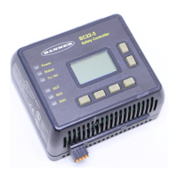
SC22-3 Safety Controller
Instruction Manual
Appendix A
A.3 Interlocked Guard or Gate
The SC22-3 safety inputs may be used to monitor
electrically interlocked guards or gates.
Safety Circuit Integrity Levels
Requirements vary widely for the level of control reliability or
safety category per ISO 13849-1 (EN954-1) in the application
of interlocked guards. While Banner Engineering always
recommends the highest level of safety in any application, it
is the responsibility of the user to safely install, operate and
maintain each safety system and comply with all relevant laws
and regulations.
The safety performance (integrity) must reduce the risk
from identified hazards as determined by the machine’s risk
assessment. See Section A.1 for guidance if the requirements as
described by ISO 13849-1 are to be implemented.
In addition to the requirements stated in this section, the design
and installation of the interlocking device should comply with
ANSI B11.19 or ISO14119.
A.3.1 Safety Interlock Switch Requirements
The following general requirements and considerations apply to
the installation of interlocked guards and gates for the purpose
of safeguarding. In addition, the user must refer to the relevant
regulations to be sure to comply with all necessary requirements.
Hazards guarded by the interlocked guard must be prevented
from operating until the guard is closed; a stop command must
be issued to the guarded machine if the guard opens while the
hazard is present. Closing the guard must not, by itself, initiate
hazardous motion; a separate procedure must be required to
initiate the motion. The safety switches must not be used as a
mechanical or end-of-travel stop.
The guard must be located an adequate distance from the
danger zone (so that the hazard has time to stop before the
guard is opened sufficiently to provide access to the hazard),
and it must open either laterally or away from the hazard, not
into the safeguarded area. The guard also should not be able to
close by itself and activate the interlocking circuitry. In addition,
the installation must prevent personnel from reaching over,
under, around or through the guard to the hazard. Any openings
in the guard must not allow access to the hazard (see OSHA
29CFR1910.217 Table O-10, ANSI B11.19, EN 294, ISO14120/
EN953 or the appropriate standard). The guard must be strong
enough to contain hazards within the guarded area, which may
be ejected, dropped or emitted by the machine.
The safety interlocking switches and actuators must be designed
and installed so that they cannot be easily defeated. They must
be mounted securely, so that their physical position can not shift,
using reliable fasteners that require a tool to remove them.
Positive-Opening Safety Interlocking Switches
Safety interlock switches must satisfy several requirements.
Each switch must provide electrically isolated contacts: at
minimum, one normally closed (N.C.) contact from each
individually mounted switch. The contacts must be of “positive-
opening” (direct-opening) design, as described by IEC 60947-
5-1, with one or more normally closed contacts rated for safety.
Positive-opening operation causes the switch to be forced
open, without the use of springs, when the switch actuator is
disengaged or moved from its home position (see the Banner
Safety Catalog for examples).
In addition, the switches must be mounted in a “positive mode,”
to move/disengage the actuator from its home position and open
the normally closed contact when the guard opens.
Magnetically Operated Safety Interlocking Switches
In higher levels of safety performance, the design of a dual-
channel magnetic switch typically uses complementary switching,
in which one channel is open and one channel is closed at all
times. This provides redundancy (two contacts) and diversity
(different principles of operation) to minimize the possibility of
the loss of the switching function due to common mode failures
(e.g., secondary magnetic fields). The circuitry or the Safety
Controller that is monitoring the magnetic switch will detect and
respond to a failure that results in the loss of the complementary
state (e.g., a short circuit between the channels, or a short circuit
to other sources of power).
Coded and non-coded magnetic switches affect the ability of the
switch to be defeated and to withstand common mode failures.
Non-coded switches are easily defeated by the presence of a
simple magnetic field and should be mounted in a concealed
position. A coded magnetic switch that uses alternating magnetic
poles should be used in applications that require higher levels of
safety performance.
The switch and its magnet must be mounted a minimum distance
from any magnetized or ferrous materials for proper operation.
If either the switch or magnet is mounted on a material that can
be magnetized (a ferrous metal, such as iron), the switching
distance will be affected. This distance will be stated by the
manufacturer.
 Loading...
