P/N 133487 55
Banner Engineering Corp. • Minneapolis, U.S.A.
www.bannerengineering.com • Tel: 763.544.3164
Product Name
Instruction Manual
Operating Instructions
6.1 Display Controller Information — PC Interface (PCI)
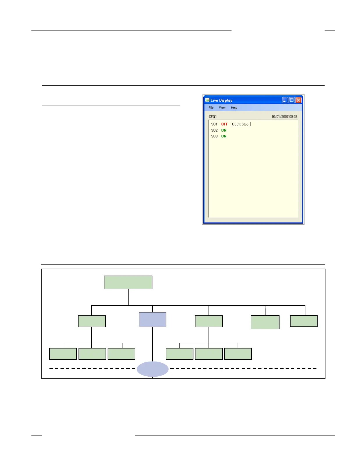
To display real-time Run mode information on a PC, the
computer must be connected to the Controller, via a USB cable
(see Section 1.3 for connection instructions). Open the Banner
Safety Controller program and click on the Live Display button in
the PCI screen to launch the Live Display screen. This feature
continually updates Run mode data and displays it in a pop-up
screen (see Figure 6-1).
The Live Display screen provides the same information that can
be viewed on the Controller’s LCD. It shows the status of each
safety output and reports on any input device or system event
that can cause a safety output to turn OFF.
6. Operating Instructions
6.2 Display Controller Information — Onboard Interface (OBI)
Figure 6-1. Live Display screen — PCI
Figure 6-2. Run mode menu selections — OBI
System Menu
Run Mode
Mode
Model Number
software and
hardware versions
Configuration
Mode
(Section 5.3)
Configuration
Summary
Fault
Diagnostics
Clear
Fault Log
View
Fault Log
View Current
Faults
Status Output
Settings
Input/Output
Mapping
Terminal
Assignments
Set Display
Contrast
← OK
ESC →
← OK
ESC →
← OK
ESC →
← OK
ESC →
Enter Password
(Section 5.3.1)