P/N 133487 113
Banner Engineering Corp. • Minneapolis, U.S.A.
www.bannerengineering.com • Tel: 763.544.3164
SC22-3 Safety Controller
Instruction Manual
Appendix C
The SC22-3 Onboard User Interface (OBI) is a tool for creating
and managing configuration files for the Safety Controller, using
the built-in features of the Controller itself. The OBI is also used
to retrieve, display and store both I/O and system status and
fault information.
The following tutorial explains the steps needed to create a
sample configuration, using the Safety Controller’s Onboard
Interface (OBI). The configuration is used to define the input
devices to be connected to the Safety Controller and to establish
relationships between those input devices and the Safety
Controller outputs.
Important: This tutorial is not intended to provide a
comprehensive lesson about every feature the Safety Controller
and OBI offer. Rather, it is designed to provide the basic skills
and processes needed to explore the features on your own. It
also is not intended to cover the operational requirements of the
SC22-3 Safety Controller. For complete operational instructions,
read Sections 1–8 of this manual.
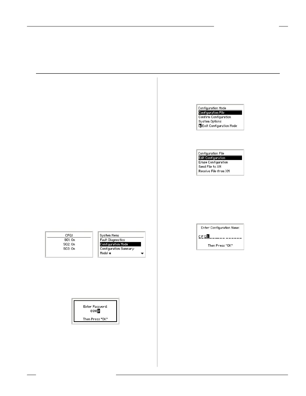
Enter Configuration Mode
The first step in creating a configuration is entering Configuration
mode. To enter Configuration mode from the Run mode display,
press OK to display the main System Menu. At the System
Menu, press the Down arrow button until Configuration Mode is
highlighted on the display, then press OK.
Enter Password
The default password is 0000. Use the left/right arrow keys to
select the password digit to change. Use the up/down arrow
buttons to change the selected password digit.
When the password is entered, press OK to enter Configuration
mode.
Read the caution that the safety outputs will turn OFF when
Configuration mode is entered, and press OK.
Appendix C. Configuration Tutorial — Onboard Interface (OBI)
Edit Configuration
To edit the configuration from the Configuration Mode menu,
select Configuration File and press OK.
When the Configuration File menu is displayed, select Edit
Configuration and press OK.
The first property of the configuration that can be changed is its
name.
Use the left/right arrow keys to select the character to be
changed (up to 16 characters).
Use the up/down arrow keys to change the character (choices A-
Z, 0-9, -, +, or space), and press OK.
Add Input Devices
In this tutorial we will add the following input devices:
• Emergency stop (E-stop) input
• Gate switch input
• Two-hand control input
• Reset input
• Optical sensor input
• External device monitoring inputs
• Mute sensor pair input
NOTE: Safety mat, protective stop, rope pull, enabling device,
and bypass switch devces are not covered in this
tutorial.