36 P/N 133487
Banner Engineering Corp. • Minneapolis, U.S.A.
www.bannerengineering.com • Tel: 763.544.3164
SC22-3 Safety Controller
Instruction Manual
Configuration — PC Interface
4.3 Building a Configuration
Install the software on your computer. Double-click on the
Banner Safety Controller icon . Read and understand the
warning on the Start-up page, and click OK. The main PCI
screen should appear.
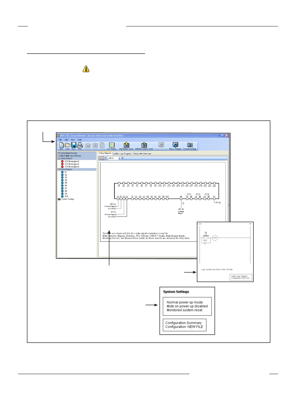
Figure 4-3. PCI main screen before configuration
The three support documents, if opened at this point, show the
following information:
• The Wiring Diagram shows its numbered terminals without
any logic circuit elements in place. The only terminal
configured by default is the System Reset (SR) terminal.
• The Ladder Logic Diagram shows the vertical lines
representing +24V and 0V dc and the system reset circuit.
• The Configuration Summary shows only some default
system settings.
Tool bar
Wiring
Diagram
Ladder Logic
Diagram
Configuration Summary