P/N 133487 37
Banner Engineering Corp. • Minneapolis, U.S.A.
www.bannerengineering.com • Tel: 763.544.3164
SC22-3 Safety Controller
Instruction Manual
Configuration — PC Interface
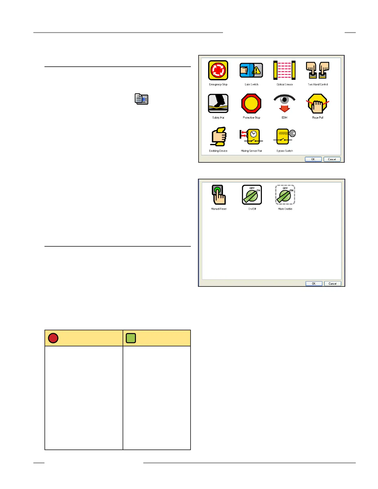
Figure 4-5. Safety Input Device Selection menu
Figure 4-6. Non-Safety Input Device Selection menu
4.3.1 Create a New Configuration
Open the software program, and a new un-named file is created.
You may name the Configuration and the Author, and establish
the system settings at this time.
Double-click the System Settings icon , on the right-
hand side of the Tool Bar.
When the pop-up menu appears, name the configuration file,
using up to 16 alphanumeric characters.
Add your name in the Author’s name box (up to 10 characters;
abbreviate as needed).
Keep or change the default system settings:
Power up mode: Auto, Manual, or Normal (default),
see Section 1.5.4
Mute on power up: ON or OFF (default),
see Section 1.5.4
Monitored system reset: OFF or ON (default),
see Section 3.4
When complete, click OK.
4.3.2 Add an Input Device
Click the Add Safety Input icon and the Safety Input Device
selection menu appears (Figure 4-5). It displays the device
types the Controller can accommodate. If the non-safety input
icon is clicked, the Non-Safety Input Device selection menu
appears (Figure 4-6). While their functions differ, the procedure
to add and configure the two types of devices is virtually
identical. Click on the appropriate icon to select the desired
device and click OK (or double-click on the icon).
NOTE: Refer to Appendix A for more information about each of
the input device types.
Safety Input
Devices
Non-Safety
Input Devices
• Emergency stop button
• Rope pull
• Gate (interlock) switch
• Optical sensor – single-
/multiple-beam sensors, safety
light curtain, area scanners, etc.
• Two-hand control device
• Safety mat
• Protective stop – miscellaneous
devices
• Enabling device
• Muting sensors
• Bypass switches
• External device monitoring
(EDM) contacts
• Manual reset switch
• ON/OFF switch
• Mute enable switch