38 P/N 133487
Banner Engineering Corp. • Minneapolis, U.S.A.
www.bannerengineering.com • Tel: 763.544.3164
SC22-3 Safety Controller
Instruction Manual
Configuration — PC Interface
Once an input device is selected, the Properties menu for that
device pops up. This menu presents the properties that must
be established for each type of input device. The user-defined
properties include (depending on the device):
• Name — The name (or ciruit designation) of each specific
device (not device type)
• Circuit Type — A list of the types of contact or solid-state
circuits that can be used for that device type
• Reset Logic — Automatic (Trip mode) and Manual (Latch
mode) options for that device
• Input Terminal Assignment — These are assigned automatically
but can be changed to any unused input terminal.
• I/O map — Establishes relationships between input devices and
outputs
NOTE: Input device properties and functions are discussed in
Section 3.2 and Appendix A.
Follow the configuration steps as they appear on the screen (see
Figure 4-7).
Name: Change the name to something meaningful to you, such
as: E-STOP1. Any input device can be renamed during the
configuration process.
Circuit Type: Select the appropriate circuit type from the drop-
down menu for your device. The selected circuit type will appear
in the input terminals diagram, with automatically assigned
terminal numbers; the terminal numbers can be reassigned using
the drop-down menus. The plus signs at S13 and S15 (see
Figure 4-7) designate that these terminals supply the +24V dc
source for the device contacts.
NOTE: See Appendix A for more information about safety
circuit integrity levels and the capabilities of each
circuit type.
Reset Logic: Select between Manual or Automatic Reset from
the drop-down menu.
Mapping: Map each safety input device to one or more safety
outputs (at least one must be selected) by checking or un-
checking the boxes. (Just click on a box to select or deselect it.)
If the safety input device is a muting sensor, a bypass switch, or
a mute enable sensor, map those inputs to at least one of the
other safety input devices.
When a safety input device with manual reset is added, a new
window automatically appears to add a reset input device for that
device. Any safety input device which keeps the default Manual
reset logic setting requires a reset for any safety output mapped
to that device. A separate reset may be assigned for each safety
output.
The wiring diagram will begin to populate with your chosen
device(s), as will the ladder logic diagram and configuration
summary.
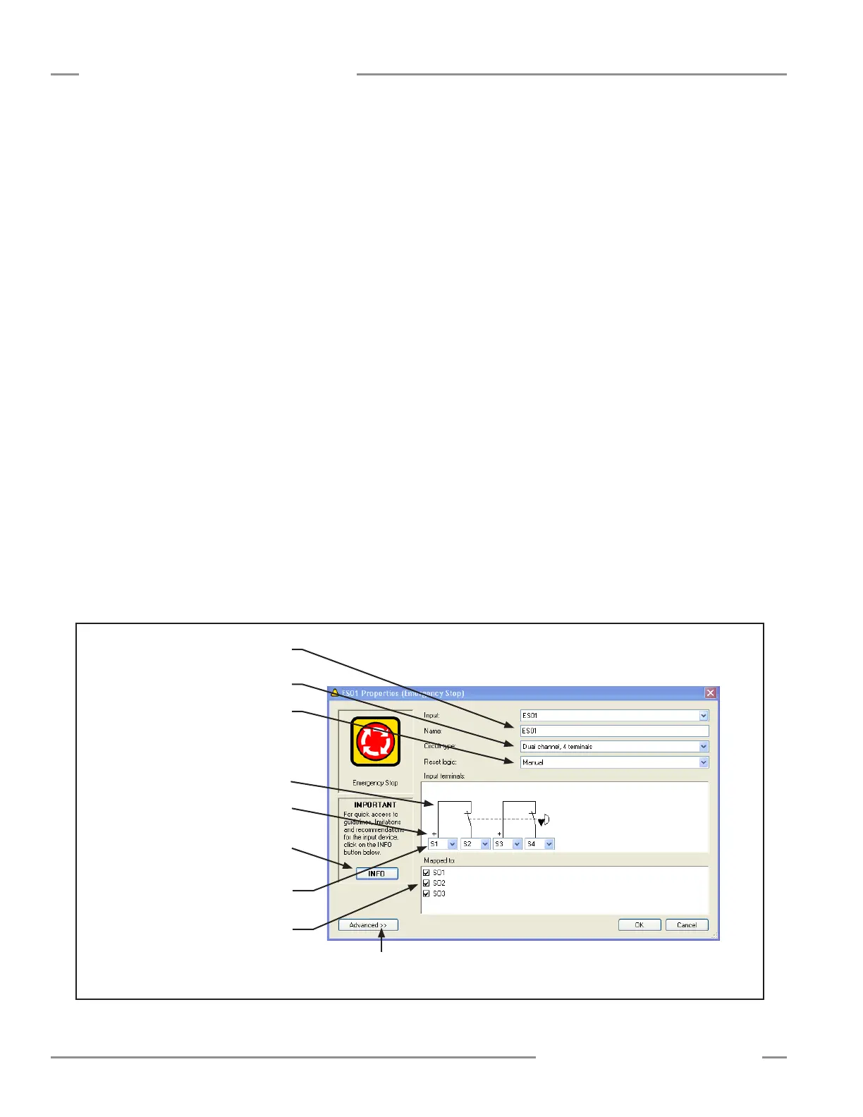
Figure 4-7. Safety Input Device Properties screen
Use the drop-down menus to change the
terminal assignments
Map each device to any
1, 2, or 3 safety outputs
Type in a name for the device
Select a circuit type from the
drop-down menu
Select the reset logic from
the drop-down menu
Depicts the selected circuit type
and terminal assignments
+ indicates the terminal that supplies
the +24V dc source for the device
Info button directs you to the
appropriate section in Appendix A.
Advanced settings are dependent on device
type (e.g., debounce time settings)