P/N 133487 39
Banner Engineering Corp. • Minneapolis, U.S.A.
www.bannerengineering.com • Tel: 763.544.3164
SC22-3 Safety Controller
Instruction Manual
Configuration — PC Interface
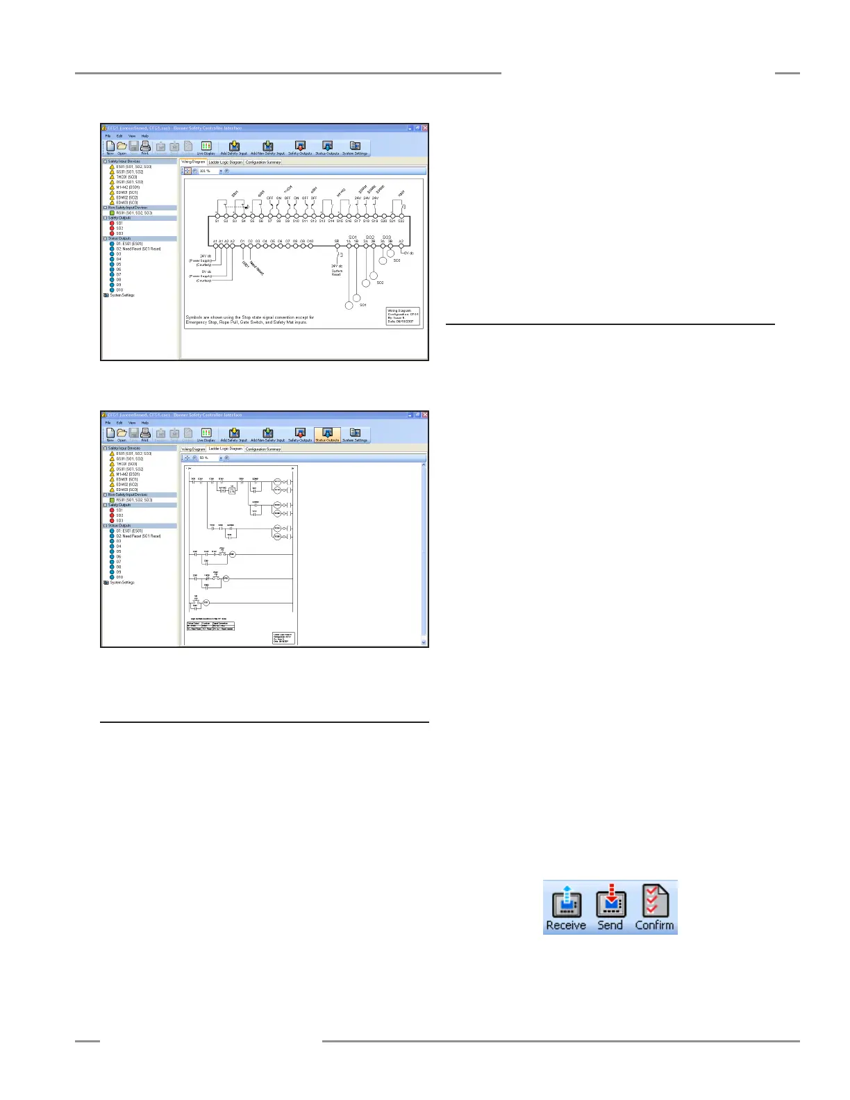
Figure 4-8. Wiring diagram populates with devices and output
mapping
Figure 4-9. Ladder logic diagram develops along with wiring
diagram
4.3.3 Finish the Configuration
Repeat the steps in Section 4.3.2 to include additional safety or
non-safety input devices.
Select Safety Outputs or Status Outputs from the tool bar to
configure properties for these outputs, using the same menu-
driven process as that for the inputs.
Safety Output Properties — assigned individually for each
safety output. Select the output to be configured from the drop-
down menu in the top field of the screen, and type in or select:
• Name
• Delay type and duration
Status Output Properties — assigned individually for each
status output. Select the output to be configured from the drop-
down menu in the top field of the screen, and type in or select:
• Name
• Function (track input, track output, system lockout status, I/O
fault status, system waiting for reset, output waiting for reset,
mute status, or unassigned)
• Source (depending on function selected)
• Signal convention (depending on function selected)
4.3.4 Save and Confirm the Configuration
You will need to confirm this new configuration before it can be
used in a safeguarding application. A 4-digit Controller password
is required to save and confirm a configuration and to enable it
to run on a Safety Controller. The confirmation process has two
parts:
1. Code validation: The microcontrollers in the SC22-3 receive
and check a copy of the configuration to be sure that all
safety-critical settings are appropriate (all device settings,
control relationships, logic functions and other parameters are
valid).
2. Configuration verification: When the validation step is
complete, the Controller saves the configuration to the internal
non-volatile memory, reads it back from memory, and sends
a copy of the stored file back to the PCI for a manual content
verification that the user performs.
To confirm a configuration:
□ 1. Save the configuration file to the PC:
• Go to File > Save
• Name the configuration file and select a file location on
your computer.
• Click Save
□ 2. Connect the SC22-3 Controller to the PC using the USB
cable (see Section 1.3.1).
□ 3. Apply 24V dc power to the Controller.
When the powered Controller is properly connected with
the computer, the Receive, Send and Confirm buttons in
the screen’s tool bar become active and convert from gray
scale to color.