4 P/N 133487
Banner Engineering Corp. • Minneapolis, U.S.A.
www.bannerengineering.com • Tel: 763.544.3164
SC22-3 Safety Controller
Instruction Manual
Overview
1.4 Configuring the Safety Controller
Building a configuration for the Safety Controller is a simple
process, using one of two interfaces: the push buttons and
display on the Controller itself (the Onboard Interface, or OBI) or
the PCI software program included on the enclosed CD
(p/n 134534). The process comprises three main steps:
1. Define the safeguarding application (risk assessment).
• Determine the required devices
• Determine the required level of safety
2. Build the configuration.
• Select safety input device types and circuit connections
• Map each input to one or more safety outputs, or to other
input devices
• Set optional safety output ON- or OFF-time delays
• Select non-safety input device types and circuit connections,
if needed
• Assign status output signals, if needed
• Create configuration name, file name, date, author name,
and notes
3. Confirm the configuration.
• Controller verifies that the desired configuration is valid.
• User confirms that the configuration is what is expected.
1.4.1 Onboard Interface (OBI)
The Safety Controller can be configured using its built-in push
buttons and LCD screen, the Onboard Interface (OBI). The LCD
display provides I/O device and system status information for any
event that causes one or more of the safety outputs to turn OFF.
The display is used in conjunction with the six push buttons to:
• Create or modify password-protected configurations,
• Retrieve fault log information,
• Review device wiring detail and I/O logic relationships, and
• Display I/O device fault details and likely remedial steps.
NOTE: Onboard Interface functions are covered in more detail
in Section 5 and the OBI tutorial, Appendix C.
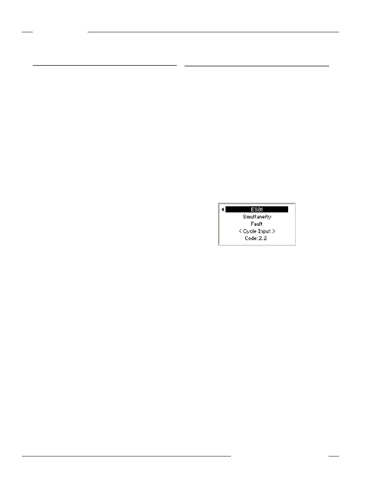
Accessing Fault Codes
The Fault codes are displayed in the last line of the OBI fault
diagnostics menu (see example below). Refer to Sections 5 and
8 for more information.