P/N 133487 77
Banner Engineering Corp. • Minneapolis, U.S.A.
www.bannerengineering.com • Tel: 763.544.3164
SC22-3 Safety Controller
Instruction Manual
Appendix A
Monitoring Series-Connected Safety Interlock Switches
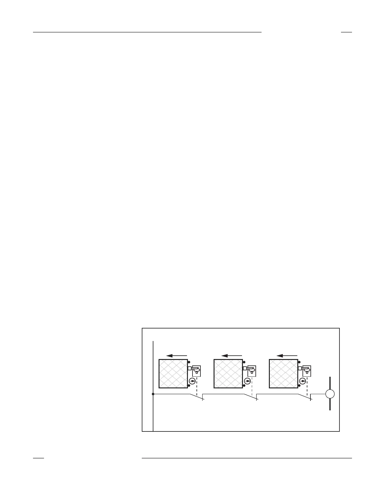
When monitoring two individually mounted safety switches (as
shown in Figure A-2), a faulty switch will be detected if it fails
to switch as the guard opens. In this case, the Controller will
de-energize its safety outputs (OSSDs) and disable its reset
function until the input requirements are met (i.e., the faulty
switch is replaced). However, when multiple safety interlock
switches are series-connected, the failure of one switch in the
system may be masked or not be detected at all (refer to Figures
A-3 and A-4).
Series-connected interlock switch circuits may not meet OSHA
Control Reliability or ISO 13849 (EN954-1) Safety Category 4
requirements because of the potential of an inappropriate reset
or a potential loss of the safety stop signal. This is due to the
typical inability to fault exclude the failure of the safety interlock
switch. A multiple connection of this type should not be
used in applications where loss of the safety stop signal or
an inappropriate reset can lead to serious injury or death.
The following two scenarios assume two positive-opening safety
switches on each guard, both connected in series to switches of
a second guard:
1. Masking of a failure. If a guard is opened but a switch fails
to open, the redundant safety switch will open and cause
the Controller to de-energize its outputs. If the faulty guard
is then closed, both Controller input channels also close,
but because one channel did not open, the Controller will
not reset. However, if the faulty switch is not replaced and a
second “good” guard is cycled (opening and then closing both
of the Controller’s input channels), the Controller considers
the failure to be corrected. With the input requirements
apparently satisfied, the Controller allows a reset. This
system is no longer redundant and, if the second switch fails,
may result in an unsafe condition (i.e., the accumulation of
faults resulting in loss of the safety function).
2. Non-detection of a failure. If a good guard is opened,
the Safety Controller de-energizes its outputs (a normal
response). But if a faulty guard is then opened and closed
before the good guard is re-closed, the faulty guard is not
detected. This system also is no longer redundant and may
result in a loss of safety if the second safety switch fails to
switch when needed.
The systems in either scenario do not inherently comply with
the safety standard requirements of detecting single faults
and preventing the next cycle. In multiple-guard systems
using series-connected safety switches, it is important to
periodically check the functional integrity of each interlocked
guard individually. Operators, maintenance personnel, and
others associated with the operation of the machine must
be trained to recognize such failures and be instructed to
correct them immediately.
Open and close each safeguard separately while verifying that
the Controller outputs operate correctly throughout the check
procedure. Follow each safeguard closure with a manual reset,
if needed. If a contact set fails, the Controller will not enable
its reset function. If the Controller does not reset, a switch may
have failed; that switch must be immediately replaced.
This check must be performed and all faults must be cleared, at
a minimum, during periodic checkouts. If the application can
not exclude these types of failures and such a failure could
result in serious injury or death, then the series connection
of safety switches must not be used.
Series Connection and Safety Circuit Integrity Considerations
Category 2: A single-channel interlocked guard application
typically provides a Category 2 level of circuit performance,
because a short circuit could cause loss of safety function. The
principle of fault exclusion must be incorporated into the design
and installation to either eliminate, or reduce to an acceptable
(minimal) level of risk, the possibility of faults that can result in
loss of the safety function.
Figure A-2. Category 2 circuit