50 P/N 133487
Banner Engineering Corp. • Minneapolis, U.S.A.
www.bannerengineering.com • Tel: 763.544.3164
SC22-3 Safety Controller
Instruction Manual
Configuration — Onboard Interface
5.4.3 Outputs/System Settings
Safety Outputs
This option is used to configure the safety outputs. Use the up/
down arrows to select Safety Outputs and press OK. Select the
output to configure in the resulting menu and press OK. You will
be given the opportunity to change the output’s name, and give it
an ON- or OFF-delay.
Status Outputs
This option is used to configure the status outputs. Status
outputs are configured individually. Use the up/down arrows to
select Status Outputs and press OK.
• Use the left/right arrows to select the status output to
configure (O1 to O10), and press OK.
• The Status Output Properties menu appears. This menu is
used to configure the status output to indicate:
— The status of an input device
— The status of a safety output
— A system lockout
— An I/O fault
— The need to perform a system reset
— The need to perform a reset operation on a safety output
— When an input is being muted
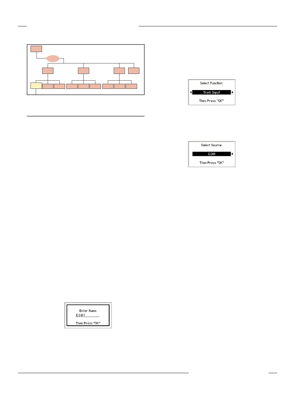
Name the Status Output — Use the up/down arrows to select
Change Name and press OK.
• Use the left/right arrows to select the character to be
changed (up to 10 characters).
• Use the up/down arrows to change the character (choices
A-Z, 0-9, -, +, or space).
• Press OK when done.
• When the display returns to the Status Output Properties
menu, the top line of the display will display the new name.
Select the function of the status output — Options are:
unassigned (no function), track input, track output, track fault
status, waiting for reset, and mute status. Use the up/down
arrows to select Select Function and press OK.
• Use the left/right arrows to select a function, then press OK.
• The display returns to the Status Output Properties menu.
Select the source for the status output function — Select
Select Source and press OK.
• Use the left/right arrows to select a device and press OK.
• The display returns to the Status Output Properties menu.
Select the signal convention — The options are:
24V = Input Active and 24V = Input Inactive (e.g., if tracking
an input; see Section 3.7 for more information).
• Use the left/right arrows to toggle between the selections
and press OK.
To save the settings for this output, select <Done> and press
OK. The display returns to the Outputs/System Settings menu.
To configure additional status outputs, select Status Outputs,
select another status output and repeat the steps above.
When the last status output is configured, press ESC to return
to the Edit Configuration menu.
System Settings
Select the output’s reset mode, power up mode and whether
mute will be active on power-up.
System Reset — Use the left/right arrows to toggle between
Monitored or Non-Monitored, and press OK.
Power Up Option — Use the left/right arrows to select among
Normal, Auto, or Manual, and press OK.
Mute on Power-Up — Use the left/right arrows to toggle
between Off or On, and press OK.
System
Settings
Terminal
Assignments
Input/Output
Mapping
Status Output
Settings
Status
Outputs
Safety
Outputs
Edit
Configuration
(Section 5.4)
Edit
Input
Delete
Input
Inputs
(Section 5.4.2)
Outputs/System
Settings
(Section 5.4.3)
Configuration
Summary
(Section 5.4.4)
← OK
ESC →
← OK
ESC →
← OK
ESC →
← OK
ESC →
← OK
ESC →
Add Input
(Section 5.5)
Save
Configuration
(Section 5.4.5)
Name
Configuration
(Section 5.4.1)
Edit Configuration continued