P/N 133487 53
Banner Engineering Corp. • Minneapolis, U.S.A.
www.bannerengineering.com • Tel: 763.544.3164
SC22-3 Safety Controller
Instruction Manual
Configuration — Onboard Interface
Configure Input Device Properties
For each input device, the following parameters must be
configured:
• Name (or use the auto-generated default name)
• Circuit type
• Terminal assignments (or use the auto-generated terminal
assignments)
• Reset logic (for some devices)
• Output mapping or input mapping (depending on device)
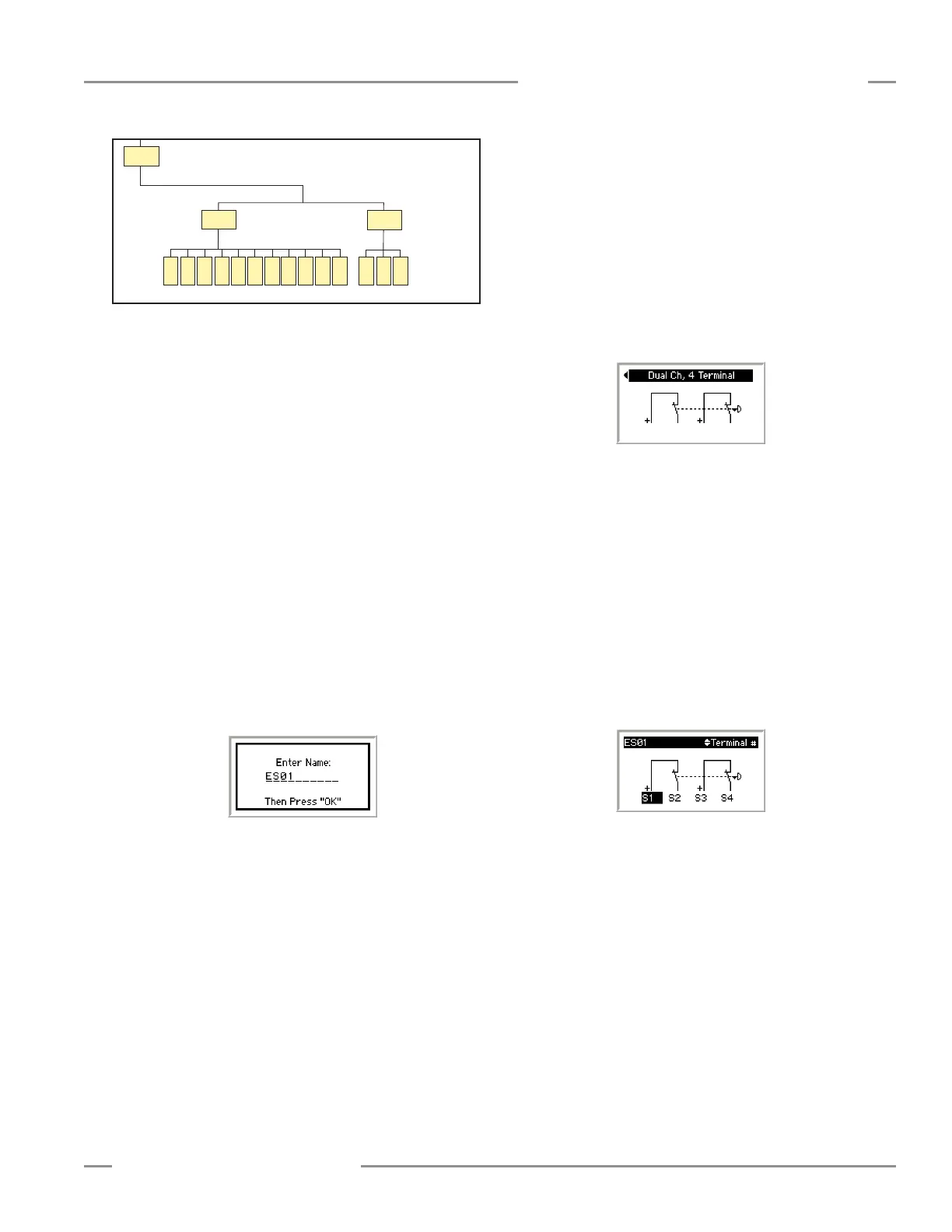
Enter Input Device Name — The Enter Name menu is
displayed. A default name automatically appears, but the device
may be renamed (up to 10 characters).
• Use the left/right arrows to select the character position.
• Use the up/down arrows to select the character for each
position (choices A-Z, 0-9, -, +, or space).
• When the screen (as shown below) shows the correct device
name, press OK.
Input Properties Menu — The Input Properties menu is used
to:
• Select the input device’s circuit type
• Edit the terminal assignments, if needed
• Select the output(s) (or input), the input will control
• Select between automatic and manual reset logic
(depending on device)
← OK
ESC →
Safety Input
(Section 5.5.1)
Non-Safety
Input
(Section 5.5.2)
← OK
ESC →
← OK
ESC →
Mute
Enable
Reset
ON/OFF
Gate
Switch
Optical
Sensor
E-Stop
Safety
Mat
Protective
Stop
Two-Hand
Control
Enabling
Device
Rope
Pull
EDM
Bypass
Switch
Mute
Sensor
Add Input
(Section 5.5)
Add an Input continued
Select the Circuit Type of the Input — Use the up/down
arrows to select Select Circuit Type, and press OK.
NOTE: See Appendix A for more information about safety circuit
integrity levels and the capabilities of each circuit type.
• The Select Circuit Type menu appears.
• Use the left/right arrows to select the desired circuit type (a
dual-channel, 4-terminal circuit type is shown below) for the
input device and press OK.
• After the circuit type is selected, the display returns to the
Input Properties menu.
Edit the Terminal Assignments — When the input circuit type
is selected, the Safety Controller automatically assigns the next
available terminals for the input device. To view and change
these terminal assignments, select Edit Terminals, and
press OK.
• Use the left/right arrow buttons to select the terminal
assignment to be changed.
• Use the up/down arrows to change the terminal assignment.
• When the terminal assignments are as desired, press OK.
NOTE: Only unassigned terminals can be assigned.
(Exception: Terminals used for a specific input device can be
assigned twice during the edit process, if the same terminals
will be used, in a different order, for this specific device.)
• After the terminal assignments are approved, the display
returns to the Input Properties menu.