601–0445 /05 Loki36
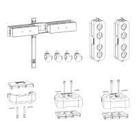
Image 3-8
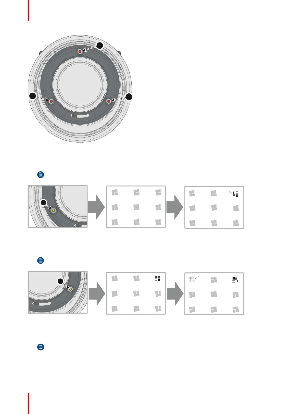
2. Adjust the left side Scheimpflug adjustment screw (reference 1) until the test image in the top right side of the
screen is in focus. Use a size 4 hex key to do this.
Note: This process may cause the other areas of the image to slide out of focus. This is totally normal.
Image 3-9
3. Adjust the right side Scheimpflug adjustment screw (reference 2) until the test image in the top left side of the
screen is in focus. Use a size 4 hex key to do this.
Note: This process may cause the other areas of the image to slide out of focus. This is totally normal.
Image 3-10
4. Adjust the top Scheimpflug adjustment screw (reference 3) until the test image in the bottom half of the screen
is in focus. Use a size 4 hex key to do this.
Note: This process may cause the other areas of the image to slide out of focus. This is totally normal.
Physical installation
 Loading...