R5906112 /09 UDX series42
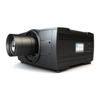
While there are several minor and barely noticeable differences between the two boards, there is one real
visual aid to tell the two variants apart. There are visual markings added on the Mark II Input board, marking
which connector supports 12G and which only supports 3G.
SEL
SEL
SEL
SEL
SDI IN SDI IN/OUT
SYNC
A
SYNC
B
SYNC
C
SYNC
D
1
Image 3-5: Mark 1 Quad Combo input board, without markings
above the SDI inputs
C D
SEL
SEL
SEL
SEL
SDI IN SDI IN/OUT
A B
SYNC SYNC SYNC SYNC
3G/12G
3G
3G
3G
2
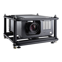
Image 3-6: Mark 2 Quad Combo input board, with 3G/12G markings
above the SDI inputs/outputs.
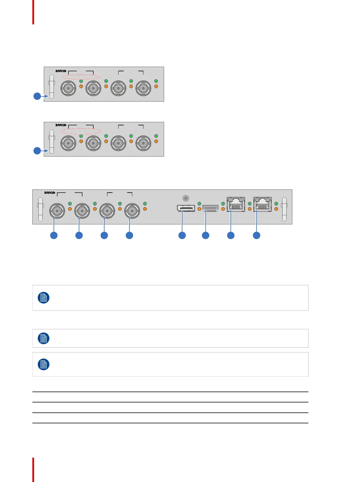
Overview Mark 2 Quad Combo Input board
SEL
SEL
SEL
SEL
SEL
SEL
SEL
SDI IN SDI IN/OUT
SEL
SYNC SYNC
A B C D
SYNC SYNC SYNC SYNC
DP HDBT 2
SYNC
HDMI HDBT 1
SYNC
3G/12G
3G
3G
3G
1 2 3 4 5 6 7 8
Image 3-7
1 Quad SDI channel A: 3G/12G input
2 Quad SDI channel B: 3G input
3 Quad SDI channel C: 3G SDI input + 3G/12G
output
4 Quad SDI channel D: 3G SDI input / output
5 DisplayPort Input
6 HDMI input
7 HDBaseT input 1
8 HDBaseT input 2
The yellow LED lights up when valid input sync is detected.
The green LED lights up when the input is selected.
The green LED lights blink when the input/output is selected and configured as output.
Input specifications – SDI Inputs
For readability, the video timings listed are summarized. For the full list of video timings, refer to the
appendices.
HD-SDI follows the SMPTE 292M standard
3G SDI follows the SMPTE 425M standard Level A
12G-SDI follows the SMPTE ST-2082-1 and ST-2082-10 standards.
Color space YCbCr
Color depth 10 bpc
Chroma sampling 4:2:2
Audio support not supported
For future release • 3D support
• Interlaced support
Input & Communication
 Loading...