22
SECTION 3 MPU6 INTRODUCTION
The following sections detail the functionality of each of the main components within the
horizon cabinet. The instructions within these sections will allow a competent engineer to
perform essential maintenance and will also aid in fault finding should a machine malfunction
occur.
3.1 MPU6 6 SYSTEM
The MPU6 6 system is a modular system comprising a number of key modules that in
combination provide a flexible, reliable I/O.
The key modules are as follows:
MPU6 board
MUX5(E) board
Reel Driver board
Switch mode power supply
The key modules are interconnected by a proprietary Barbus power/data link, which provides
D.C. power supply routing and integrates the modules into a working system. Each end of
the Barbus data link is terminated at the PSU interface board.
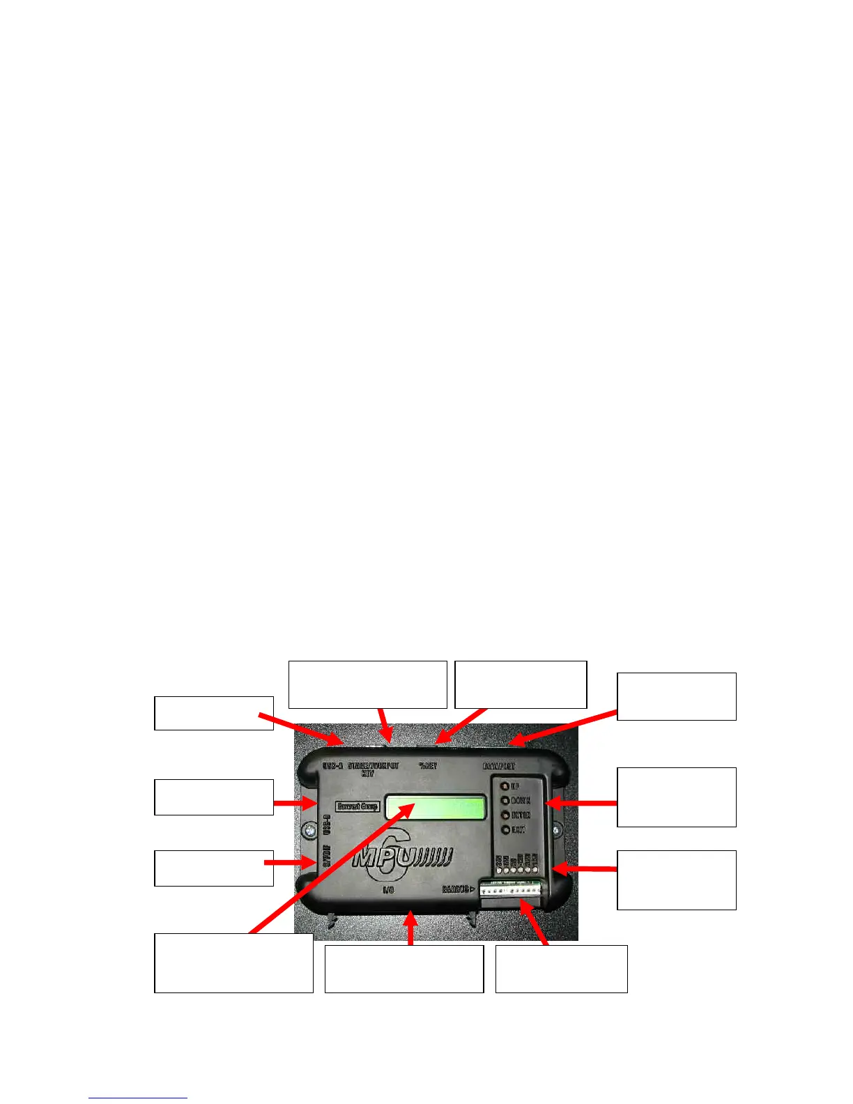
3.2 MPU6 Board
The MPU6 6 board offers numerous enhancements from its reliable & robust MPU5
ancestor, these include an integrated on board 16 character LCD display with backlight and
menu buttons, increased processor power, additional memory and USB connectors.
USB A PORT
S/P DIF Input
BARBUS
INTERFACE
USB B PORT
16 CHARACTER LCD
DISPLAY PANEL.
64-WAY CONNECTOR
PORT
DATAPORT
CONNECTOR
ON BOARD
MENU
BUTTONS
POWER
STATUS
INDICATORS
PERCENTAGE
KEY PORT
STAKES AND PRIZES
PORT