58
4.19 Buttons interface
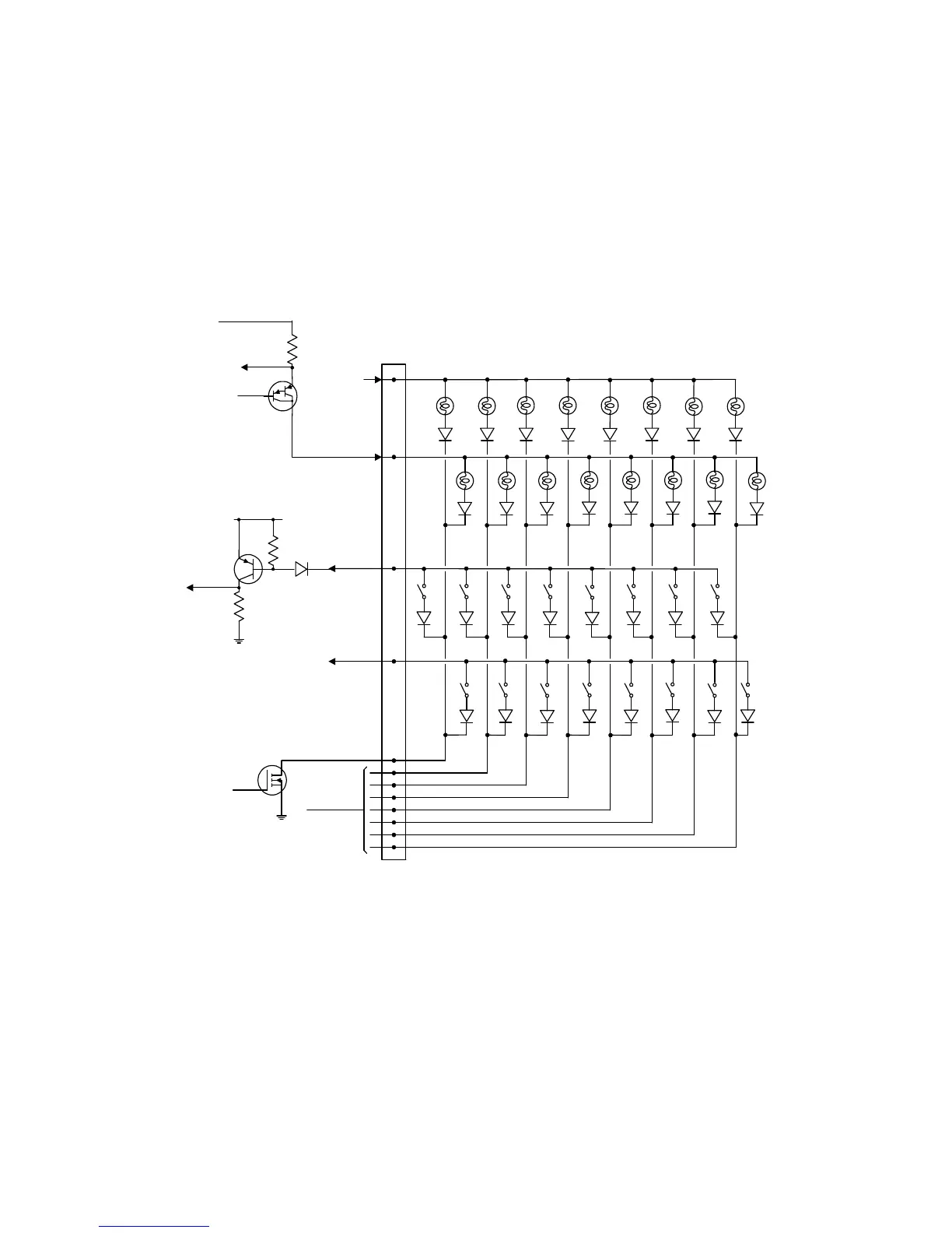
The MUX5(E) board can interface with 16 illuminated pushbuttons via a brown 13-way
BUTTONS connector having a keyway at pin position 11.
The interface's lamps and switches are each wired into a 2 x 8 matrix as shown in Fig. 29.
The diode in the switch input line protects the transistor against +34V which might appear on
the line under certain fault conditions.
Select line
BLUE
Select lines
From cpu
To current
s
ensing
circuits
+34V
LAMP DRIVE
TRANSISTOR
(1 of 2)
Lamp drive
GREEN
1
.0 ohm
F
rom cpu
2nd lamp
drive
+5V
Switch input
T
o cpu
2nd switch input
13
12
KEY
(11)
2
1
3
4
5
6
7
8
9
10
BUTTONS
SWITCH DRIVE
TRANSISTOR
(1 of 2)
SELECT
TRANSISTOR
(1 of 8)
Fig. 29. Buttons interface