62
4.24 REEL5 control board
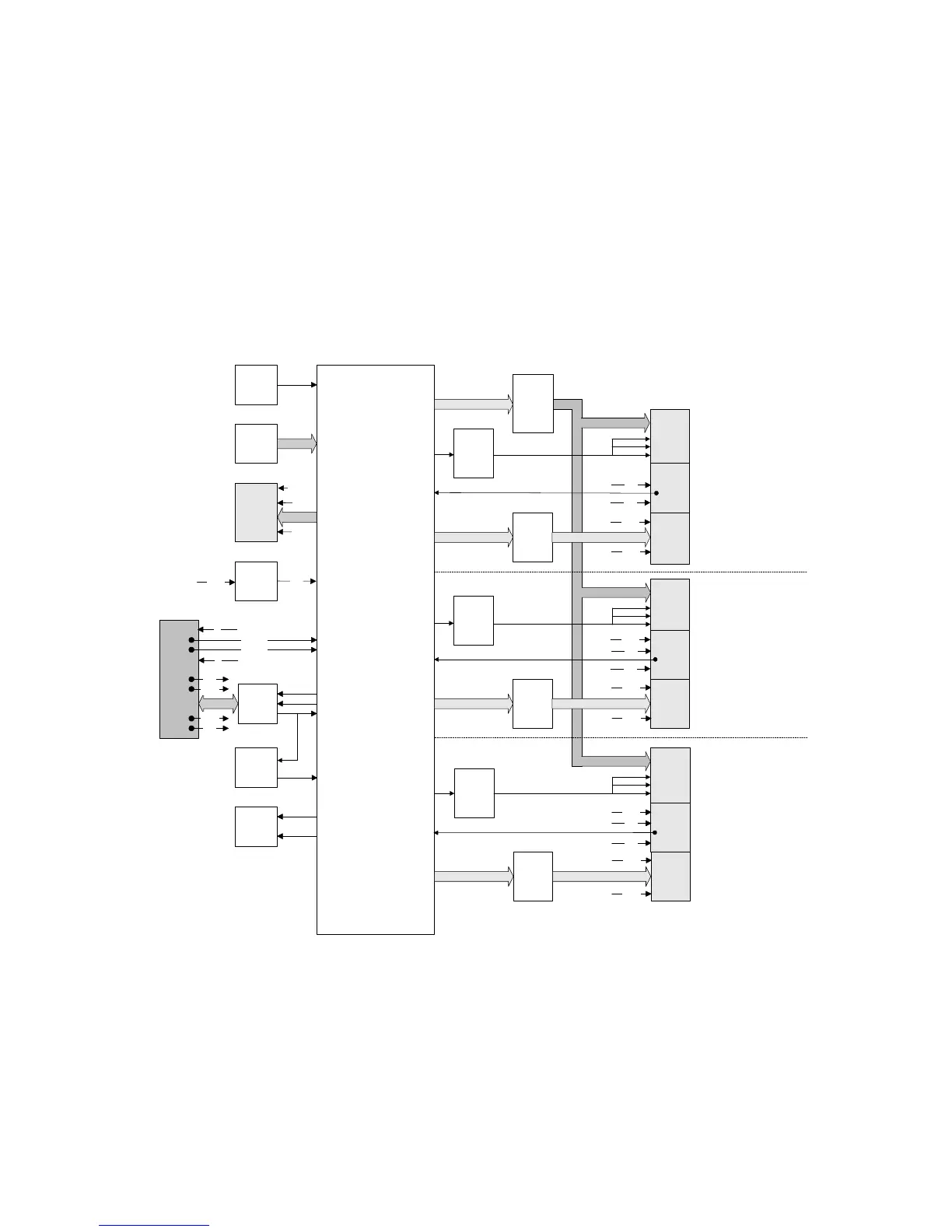
The REEL5 control board, shown in Fig. 31, provides direct control of up to five reels, under
supervision of the MPU6 board. An 8-bit on-board processor (cpu) controls each reel
independently, receiving reel positioning requirements from the MPU6 board via the Barbus
serial data link and generating position demands via 8-bit parallel ports.
Each reel is controlled via three interfaces. The reel stepper motor is driven via a REEL
interface, a LAMP interface controls the lamps illuminating the reel symbols and an OPTO
interface receives a reel marker pulse enabling the cpu to determine the reel position at any
time. An additional STROBE interface can provide strobe signals which may be used by
certain games.
L
amp
Current
S
ense
Z86C62
SCM
RS485
11
WAY
2
5
V
Reg
1
2
V
5
V
Addr1
0V
34V
12V
Addr0
0V
BARBUS
0
1
Status
LED
Reset
CCT
3
Low
S
ide
Selects
3
7
Way
3
34 V
H
igh
Side
Drive
4
Low
Side
D
rives
7
W
ay
4
12V
1
2V
4
5
Way
5V
0
V
7
Way
3
3
4 V
High
Side
Drive
4
Low
Side
Drives
7
Way
4
12V
12V
4
5
Way
5V
12V
0V
7
Way
3
34 V
High
Side
Drive
4
Low
Side
Drives
7
Way
4
12V
12V
4
5
Way
5V
12V
0V
LAMP1
OPTO1
REEL1
REEL 1
REEL 2
REEL 5
M
otor
Type
Links
4
6
W
ay
STROBE
PORT
12V
5V
2
0V
Fig. 31. REEL5 control board block diagram