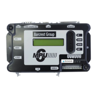
34
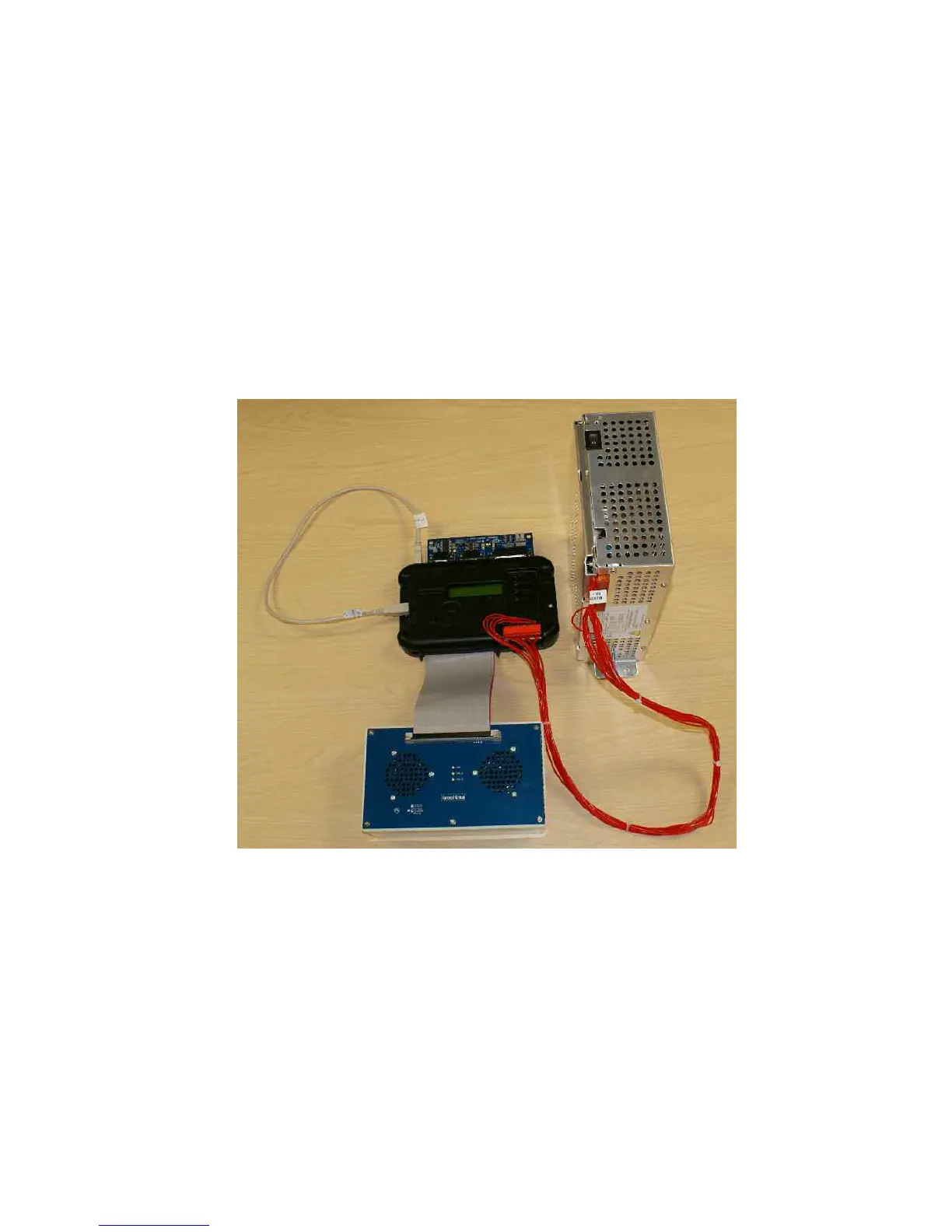
3.5.5 Test Jig Set Up
Connect up the following components as shown in the image below
1. Connect the USB lead between the USB A and B Ports.
2. Connect the D type test board to the Stake/Jackpot, Percentage and Dataport connectors
3. Connect the red Barbus power harness between the power supply and the MPU6 Barbus
connector.
4. Connect the 64-way ribbon cable between the MPU6 and the test panel.
5. Connect the mains lead to the power supply.